
User guide


264 www.xilinx.com System Generator for DSP User Guide
UG640 (v 12.2) July 23, 2010
Chapter 3: Using Hardware Co-Simulation
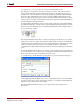
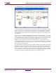
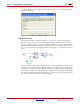
19. On the parameters dialog box, switch to the Output Type tab.
There are several things of interest on this tab. First, you set the output data type as an int32
to match the filter data path output width of 32-bits. Note the design will not simulate
unless these widths match. Secondly, you choose an output dimension that is 4095 words
deep in the Output dimensions field. Finally, you tell the block to generate frame-based
output since frame data types are required by the downstream Unbuffer block.
20. Close the parameters dialog box.
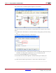
The Simulink Unbuffer block takes the frame data from the Shared Memory Read block
and deserializes it into sequential scalar values. The Simulink Unbuffer block also
introduces a sample rate change in the diagram. Because the input sample period to the
block is 4095, and the frame size is 4095 words, the Unbuffer block output sample period is
1. This works out nicely since you have data moving through the overall system at an
effective sample period of 1.
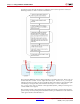
Because the Shared Memory Write and Read block operate on integer values, you must
insert Simulink type conversion blocks into the diagram so that the data is interpreted
correctly in various portions of the model. The in_data_conv subsystem converts the
Simulink doubles into 16-bit integer values that can be interpreted appropriately by the
FPGA hardware. On the output side, the out_data_conv subsystem converts the 32-bit
integers into 32-bit Simulink fixed-precision values.
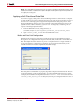
Before simulating the design, you must add the hardware co-simulation block you created
from the previous design.