
User guide

260 www.xilinx.com System Generator for DSP User Guide
UG640 (v 12.2) July 23, 2010
Chapter 3: Using Hardware Co-Simulation
Compiling for Hardware Co-simulation
You will now compile the design for hardware co-simulation. Before performing the
following steps, ensure that you have an appropriate hardware co-simulation board
installed in System Generator and attached to your PC. In this example, you only want to
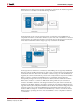
compile the portion of the design that resides inside the hw_cosim subsystem. This is
because you want the CA To FIFO and VA From FIFO blocks to remain in software as part
of the design test bench (while their partner shared FIFOs are compiled into FPGA logic).
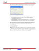
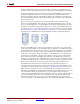
5. Double-click on the System Generator block in the hw_cosim subsystem to open the
System Generator dialog box.
6. From the Compilation submenu, choose an appropriate hardware co-simulation
target. Note that although you use the Point-to-point Ethernet hardware co-simulation
interface in this example, any installed hardware co-simulation board (e.g., a board
that supports JTAG co-simulation) will suffice.
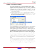
7. Press the Generate button on the System Generator dialog box to generate the design.
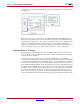
A new hardware co-simulation library and block are created once System Generator
finishes compiling the design. Note that the new hardware co-simulation block does not
have any input or output ports. This is because the subsystem that was compiled did not
contain gateway blocks or Simulink ports. Instead, all connections to other Simulink blocks
are handled implicitly through shared memories that were compiled into the FPGA.
Because you left the To FIFO and From FIFO blocks as part of the software testbench, the
software FIFOs will automatically attach to the FIFOs in hardware at the beginning of
simulation.
It is often necessary to examine the type and configuration of a shared memory that was
compiled for hardware co-simulation. The information about each shared memory is
available in a Shared Memories tab on the hardware co-simulation block dialog box. This
tab contains a tree view of information about each shared memory embedded in the
design.
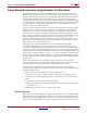
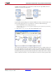
8. Double-click on the hardware co-simulation block to open the parameters dialog box.
9. Select the Shared Memories tab in the hardware co-simulation block dialog box.
The tree-view contains information about the CA and VA shared FIFO blocks that were
compiled. If your co-simulation design contains other shared memory blocks, information
about these blocks will also be displayed here. You may expand or collapse shared