
User guide

258 www.xilinx.com System Generator for DSP User Guide
UG640 (v 12.2) July 23, 2010
Chapter 3: Using Hardware Co-Simulation
compiled into the FPGA for hardware co-simulation. You consider everything else in the
design (i.e., all blocks in the top-level) as the design test bench.
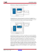
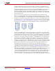
Pushing into the hw_cosim subsystem, you have an n-tap MAC FIR Filter block that
implements the design data path. Wrapping the filter are From FIFO and To FIFO blocks
that provide the input and output buffers, respectively. The MAC filter in the example
design is a modified version of the n-tap MAC filter available in the System Generator DSP
Reference Blockset library. In the example, the filter is modified to include valid in and
valid out ports in order to support the FIFO flow control scheme.
In total, there are four shared memory blocks in the design that define the CA and VA
shared FIFO pairs. In truth, you only need the shared FIFO blocks contained inside the
hw_cosim subsystem to successfully compile the design for hardware co-simulation.
Because you would like to simulate the complete design, including FPGA hardware, you
include a CA To FIFO block and VA From FIFO block in the test bench logic. These shared
FIFO blocks are responsible for writing and reading test data from the shared FIFOs in the
hw_cosim subsystem.
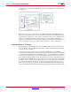
Unfiltered data from the din Gateway In block is written into the CA To FIFO block. At this
point, the CA From FIFO block in the hw_cosim subsystem reads data from the FIFO and
writes it into the MAC filter. The MAC filter in turn processes the data and writes it into the
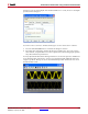
output buffer, represented by the VA To FIFO block. Lastly, the VA From FIFO block in the
top-level reads the data and sends it to the Scope block for visualization.
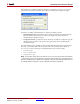
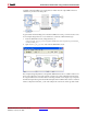
For this example, you have chosen a maximum buffer size of 4K. This parameter is set by
specifying 4K for the Depth parameter on the CA From FIFO and VA To FIFO block dialog
boxes. Note that because shared FIFOs are implemented using asynchronous FIFO