
User guide

252 www.xilinx.com System Generator for DSP User Guide
UG640 (v 12.2) July 23, 2010
Chapter 3: Using Hardware Co-Simulation
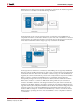
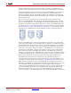
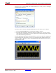
Note: You may find the names of all shared memories embedded inside an FPGA co-simulation
design by viewing the Shared Memories tab on a hardware co-simulation block.
Restrictions on Shared Memories
The following restrictions apply to System Generator designs that use shared memory,
register, or FIFO blocks in conjunction with hardware co-simulation:
• The access protection mode of a shared memory may not be modified once it has been
compiled for hardware co-simulation.
• Shared memory address port widths are limited to 24-bits (or less), allowing an
address space of 16,777,216 words;
• Shared memory, register, and FIFO data port widths are currently limited to 32-bits or
less.
• Shared memories and FIFOs are implemented in hardware using block memories;
neither distributed nor external memory implementations are currently supported.
• No more than two shared memories with the same shared memory name may be
compiled for hardware co-simulation.
• Two or more hardware co-simulation blocks that have shared memory names in
common may not concurrently be used in the same design.
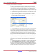
Specifying Xilinx Tool Flow Settings
When a design is compiled for System Generator hardware co-simulation, the command
line tool, XFLOW, is used to implement and configure your design for the selected FPGA
board. XFLOW defines various flows that determine the sequence of programs that should
be run on your design during compilation. There are typically multiple flows that must be
run in order to achieve the desired output results, which in the case of hardware co-
simulation targets, is a configuration bitstream.
System Generator uses two flows, implementation and configuration, in order to produce a
configuration bitstream. The implementation flow is responsible for compiling the
synthesis tool netlist output (e.g., EDIF or NGC) into a placed and routed NCD file. To
accomplish this, it runs the Xilinx tools NGDBuild, MAP, and PAR. The implementation
flow can also execute TRACE (for timing analysis purposes), although this program is
typically omitted in order to expedite the compilation process. The configuration flow runs
the tools necessary to create an FPGA bitstream, using the fully elaborated NCD file as
input.
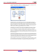
The implementation and configuration flow types have separate XFLOW options files
associated with them. An XFLOW options file declares the programs that should be run for
a particular flow, and defines the command line options that are used by these tools. Each
hardware co-simulation compilation target provides options files that define the default
configuration options for these tools. Sometimes you may want to use options files that use
settings that differ (e.g., to specify a higher placer effort level in PAR) from the default
options provided by the target. In this case, you may create your own options files, or edit
the default options files to include your desired settings.