
User guide

248 www.xilinx.com System Generator for DSP User Guide
UG640 (v 12.2) July 23, 2010
Chapter 3: Using Hardware Co-Simulation
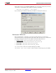
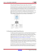
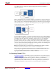
System Generator performs high speed data transfers between the host PC and FPGA. The
semantics associated with these transactions are shown in the figure below. .
Co-Simulating Shared Registers
A To Register, From Register or shared register pair may be generated and co-simulated in
FPGA hardware. Here and throughout this topic, a shared register pair is defined as a To
Register block and From Register block that specify the same name (e.g., 'Bar'). In
hardware, a shared register is implemented using a synthesizable register component (for
VHDL) or a module (for Verilog). This topic explains how single shared registers and
shared register pairs behave during hardware co-simulation.
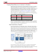
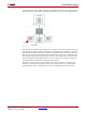
When a design that includes a shared register pair is compiled for hardware co-simulation,
the pair is replaced by a single register instance. Both sides of the register attach to user
design logic; that is, logic that originated from the original System Generator model.
Unlike designs compiled using the Multiple Subsystem Generator
block, all ports on the
hardware register attach to signals in the same clock domain. In this case, control of the
register is not shared between the PC and FPGA hardware since all register ports are
attached to user design logic. Compiling a shared register pair into hardware is equivalent
to compiling a System Generator Register
or Delay block.
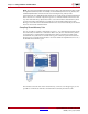
Compiling a single To Register or From Register block for hardware co-simulation results
in a different type of implementation. A single register is still created to replace the To or
From Register block. Only in this case, the register connects to both the PC interface and
FPGA logic. The side of the register in the original model remains connected to user design
logic. The other side of the register attaches to data and control ports that interface with the
PC.
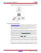
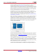
For example, in the following figure, when a From Register block is compiled for hardware
co-simulation, the dout register port remains attached to the user design. The din, ce, and
clk register ports attach to control and data ports that interface with the PC. In this way, it