
User guide

System Generator for DSP User Guide www.xilinx.com 237
UG640 (v 12.2) July 23, 2010
Ethernet Hardware Co-Simulation
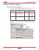
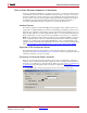
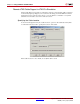
3. Use the Ethernet tab to configure the Ethernet Interface Settings:
♦ From the Host interface panel, use the pulldown list to select the appropriate
network interface for co-simulation.
Note:
The pull down list only shows those Ethernet-compatible network interfaces installed
on the host, which support 10/100/1000 Mbps, and are currently enabled and attached to an
active Ethernet segment. If the target interface is not listed as expected, examine the
connection and click the Refresh button to update the list.
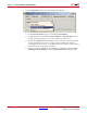
♦
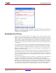
The information box beneath the pull-down list provides the details about the
selected interface. Examine the information to ensure the appropriate interface is
chosen, and adjust the network settings in the operating system when necessary.
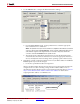
4. Depending on which configuration method is chosen, the MAC address in the FPGA
interface panel may need to be changed.
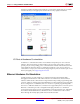
a. For Point-to-point Ethernet-based configuration:
Observe the MAC address displayed on the LCD screen of the target board when the
configuration boot-loader is running. Change the FPGA MAC address in the co-
simulation block if the default value does not match the target board. Refer to Optional
Step to Set the Ethernet MAC Address and the IPv4 Address for details about
assigning the MAC address on a ML402 board.
Select an Interface