
User guide

232 www.xilinx.com System Generator for DSP User Guide
UG640 (v 12.2) July 23, 2010
Chapter 3: Using Hardware Co-Simulation
Clocking Modes
There are several ways in which a System Generator hardware co-simulation block can be
synchronized with its associated FPGA hardware. In single-step mode, the FPGA is in
effect clocked from Simulink, whereas in free-running clock mode, the FPGA runs off an
internal clock, and is sampled asynchronously when Simulink wakes up the hardware co-
simulation block.
Single-Step Clock
In single-step clock mode, the hardware is kept in lock step with the software simulation.
This is achieved by providing a single clock pulse (or some number of clock pulses if the
FPGA is over-clocked with respect to the input/output rates) to the hardware for each
simulation cycle. In this mode, the hardware co-simulation block is bit-true and cycle-true
to the original model.
Because the hardware co-simulation block is in effect producing the clock signal for the
FPGA hardware only when Simulink awakes it, the overhead associated with the rest of
the Simulink model's simulation, and the communication overhead (e.g. bus latency)
between Simulink and the FPGA board can significantly limit the performance achieved
by the hardware. As a general rule of thumb, as long as the amount of computation inside
the FPGA is significant with respect to the communication overhead (e.g. the amount of
logic is large, or the hardware is significantly over-clocked), the hardware will provide
significant simulation speed-up.
Free-Running Clock
In free-running clock mode, the hardware runs asynchronously relative to the software
simulation. Unlike the single-step clock mode, where Simulink effectively generates the
FPGA clock, in free-running mode, the hardware clock runs continuously inside the FPGA
itself.
In this mode, simulation is not bit and cycle true to the original model, because Simulink is
only sampling the internal state of the hardware at the times when Simulink awakes the
hardware co-simulation block. The FPGA port I/O is no longer synchronized with events
in Simulink. When an event occurs on a Simulink port, the value is either read from or
written to the corresponding port in hardware at that time. However, since an unknown
number of clock cycles have elapsed in hardware between port events, the current state of
the hardware cannot be reconciled to the original System Generator model. For many
streaming applications, this is in fact highly desirable, as it allows the FPGA to work at full
speed, synchronizing only periodically to Simulink.
In free-running mode, you must build explicit synchronization mechanisms into the
System Generator model. A simple example is a status register, exposed as an output port
on the hardware co-simulation block, which is set in hardware when a condition is met.
The rest of the System Generator model can poll the status register to determine the state of
the hardware.
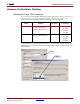
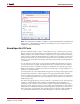
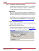
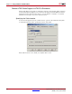
Selecting the Clock Mode
Not every hardware board supports a free running clock. However, for those that do, the
parameters dialog box for the hardware co-simulation block provides a means to select the
desired clocking mode. You may change the co-simulation clocking mode before
simulation starts by selecting either the Single stepped or Free running radio button
under the Clocking etch box.