
User guide

204 www.xilinx.com System Generator for DSP User Guide
UG640 (v 12.2) July 23, 2010
Chapter 2: Hardware/Software Co-Design
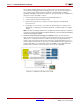
want to bring the MicroBlaze processor system into the System Generator design
environment for debugging and simulating purposes. You can take advantages of a
very complex and powerful simulation platform – Simulink, HDL (including
ModelSim and ISIM), and hardware simulations. The typical steps to accomplish this
design flow can be described as follows:
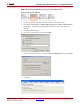
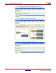
♦ Create an XPS project using the Base System Builder Wizard
♦ Create a System Generator design model
♦ Import the XPS project into a System Generator design by using the EDK
Processor block
♦ Depending on your needs, you can either perform hardware co-simulation for
debugging or validating your hardware platform or add the netlist into a bigger
design
Note:
The obvious advantage with this flow is the ability to perform the hardware co-simulation
on the processor block and its peripherals and take advantages of the rich and powerful Simulink
simulation and debugging capability.
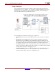
3. System Generator Dual Clock Support for EDK Processors: System Generator
supports dual clock wiring, which means that the imported processor system and the
other portion of a System Generator model are driven by two independent clock
domains. One major benefit with dual clock wiring is that the MicroBlaze processor
system and the System Generator user logic can run at different clock frequencies. For
example, MicroBlaze can comfortably operate at 100 MHz, while a DSP FIR (finite
impulse response) filter in System Generator can run at up to 400 MHz.