
User guide

202 www.xilinx.com System Generator for DSP User Guide
UG640 (v 12.2) July 23, 2010
Chapter 2: Hardware/Software Co-Design
Design Description
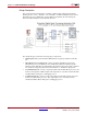
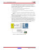
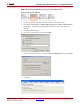
The System Generator design below includes a FIR Compiler 5.0 block with Shared
Memory blocks – From / To FIFOs. Also included is an SP601 embedded system with a
MicroBlaze processor, PLB4.6 bus, and a UART Lite peripheral, all created using the
Platform Studio BSB (Base System Builder) Wizard.
This simple design contains the following major components:
• FIR Compiler 5.0: a parameterizable FIR filter that accepts input data from the din
pin.
• MicroBlaze Processor Subsystem: contains an SP601 embedded system with a
MicroBlaze processor, PLB4.6 bus, and a UART Lite peripheral created using the
Platform Studio BSB (Base System Builder) Wizard. This subsystem will be compiled
into hardware using the System Generator hardware co-simulation design flow.
• From FIFO din block: is used to accept input data from the MicroBlaze processor and
feed it to the input din of FIR Compiler. This input data is accessible via both Simulink
and MicroBlaze during the co-debugging session.
• To FIFO dout block: is used to accept output data from the FIR Compiler dout and
feed it to the MicroBlaze processor. This output data is also accessible via both
Simulink and MicroBlaze during the co-debugging session.