
User guide

178 www.xilinx.com System Generator for DSP User Guide
UG640 (v 12.2) July 23, 2010
Chapter 2: Hardware/Software Co-Design
Tutorial Example - Designing and Simulating MicroBlaze Processor
Systems
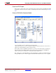
This topic shows an example on how to design and simulate a System Generator model
containing a MicroBlaze™ processor. A DSP48 co-processor is developed using System
Generator. Using the EDK Processor block, you import a MicroBlaze processor, customized
in Xilinx Platform Studio (XPS), into the System Generator model. You then attach the
DSP48 co-processor to the imported MicroBlaze processor through the automatic memory
mapping mechanisms provided by the EDK Processor block.
This tutorial uses hardware co-simulation to simulate and verify the design. In this case,
the MicroBlaze processor is compiled into hardware, while the DSP48 co-processor model
is left in the System Generator diagram for software simulation. In this example, the
hardware simulation and software simulation communicate with each other using the
point-to-point Ethernet co-simulation technology.
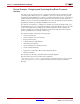
This tutorial example contains the following topics:
• Create an XPS Project
• Create a DSP48 Co-Processor Model
• Import an XPS Project
• Configure Memory Map Interface
• Write Software Programs
• Create a Hardware Co-Simulation Block
• Create a Testbench Model
• Update the Co-Simulation Block with Compiled Software
• Run the Simulation
This example uses the Xilinx Virtex®-4 ML402 Evaluation Platform.
The files used in this tutorial can be found a pathname:
<ISE_Design_Suite_tree>/sysgen/examples/EDK/DSP48CoProcessor, where
<ISE_Design_Suite_tree>/sysgen denotes the System Generator installation
directory.