
User guide

System Generator for DSP User Guide www.xilinx.com 173
UG640 (v 12.2) July 23, 2010
Designing with Embedded Processors and Microcontrollers
Designing and Exporting MicroBlaze Processor Peripherals
The Xilinx Platform Studio (XPS) tool suite allows the development of customized
MicroBlaze™ and PowerPC® processor systems. A hardware peripheral of the processor
system is called “pcore”, which consists of a bundle of design files organized according to
a specific structure. These design files describe the hardware implementation, the
connection interface, and software drivers of the XPS pcore.
The EDK Processor block in conjunction with the EDK Export Tool
allows customized
processor hardware peripherals to be designed in System Generator. A System Generator
design can be exported as an XPS pcore, which can be included and used in an XPS project.
The following tutorial illustrates the creation of a XPS pcore using System Generator. The
files used in this tutorial can be found in:
<ISE_Design_Suite_tree>/sysgen/examples/EDK/rgb2gray, where
<ISE_Design_Suite_tree>/sysgen denotes the System Generator installation
directory.
Tutorial Example - Creating MicroBlaze Peripherals in System Generator
Note: You must have EDK installed to complete this tutorial.
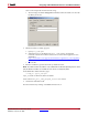
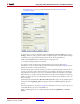
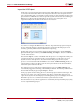
1. Open the rgb2gray model from pathname
<ISE_Design_Suite_tree>/sysgen/examples/EDK/rgb2gray.
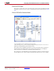
The peripheral contains three inputs, which are 32-bit red, green and blue pixel values.
These values are scaled and summed to produce a result that represents the 32-bit
grayscale value. The red, green and blue values are sourced from three shared registers
named 'red', 'green' and 'blue'. The result is written back to a shared register called 'result'.