
User guide

170 www.xilinx.com System Generator for DSP User Guide
UG640 (v 12.2) July 23, 2010
Chapter 2: Hardware/Software Co-Design
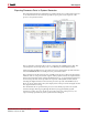
d. Double-click the PicoBlaze Instruction Display block and set the Vers ion to
PicoBlaze 3. Check the Disable Display option. Disabling the display option
allows the simulation to run without the overhead of updating the block display.
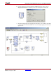
e. Find the ROM block in the Memory Library and add it to the model where
indicated. Flip the block by Right clicking on the block and selecting Format > Flip
Block. Attach the ports to the existing lines.
f. Change the Single-Step Simulation block to be in continuous mode by double
clicking on the block.
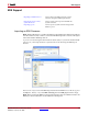
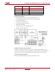
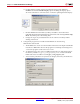
4. Configure the program store. Double click the ROM to do the following.
With the Basic tab selected:
a. The ROM block is used to store the PicoBlaze instructions. The depth of the ROM
must be set to 1024. This is because the program uses interrupts and setting brk to
1 causes the program counter to be set to 0x3FF.
b. As detailed in step 5, the code is assembled and produces an initialization file for
the memory named fill_pico_code_program_store.m. Hence the ROM
Initial Value Vector should be set to fill_pico_code_program_store.
c. To increase the performance for synchronous designs, the Latency should be set to