
User guide

168 www.xilinx.com System Generator for DSP User Guide
UG640 (v 12.2) July 23, 2010
Chapter 2: Hardware/Software Co-Design
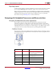
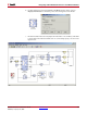
ALU
The Arithmetic Logic Unit (ALU) provides operations such as add, sub, load, and, or, xor,
shift, rotate, compare, and test. The first operand to each instruction is a register to which
the result is stored. Operations requiring a second operand can specify either a second
register or an 8-bit constant value.
Flags and Program Control
The result of an ALU operation determines the status of the zero and carry flags. The zero
flag is set whenever the result is zero. The carry flag is set when there is an overflow from
an arithmetic operation. The status of the flags can be used to determine the execution
sequence of the program using conditional program flow control instructions such as
jump and call.
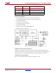
Input/Output
There are 256 input ports and 256 output ports. The port being accessed is indicated by an
8-bit address value provided on port_id. The port address can be specified in the
program as an absolute value or indirectly specified as the contents of a register. During an
input operation, the value provided to in_port is transferred into any of the 16 registers.
During an output operation, a value is transferred from a register to out_port.
Interrupt
The processor provides a single interrupt input port, brk. When interrupts are enabled,
setting brk to 1 causes the program counter to be set to memory location 0x3FF, where a
jump vector to the interrupt service routine is stored. At this time, a pulse is generated on
the ack port (two clock cycles after brk is asserted), the control flags are preserved and
further interrupts are disabled. The return instruction ensures that the end of an interrupt
routine restores the status of the control flags and specifies if future interrupts should be
enabled.
For extensive details regarding the feature and instruction set, please refer online to the
topic PicoBlaze User Resources
.
Tutorial Example - Using PicoBlaze in System Generator
In the following example, you modify a PicoBlaze program that alters the output
frequency of a Direct Digital Synthesizer (DDS) during an interrupt.
A Simulink model and PicoBlaze assembler code are provided but need modification.
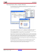
1. From the MATLAB console, change directory to
<ISE_Design_Suite_tree>/sysgen/examples/picoblaze. The following
files are located in this directory:
♦ Pico_dds.mdl – An unfinished Simulink model
♦ Pico_code.psm – Unfinished PicoBlaze code
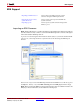
2. Open Pico_dds.mdl.
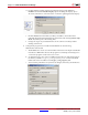
3. Modify the design.
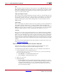
a. Find the PicoBlaze block in the Xilinx Blockset Library under Index or Control
Logic and add it to the model where indicated. The default settings of the block do
not give the same number of ports as is expected by the model. This will be
corrected in the following step. You may need to resize the block to fit into the
space allocated in the design.