
User guide

16 www.xilinx.com System Generator for DSP User Guide
UG640 (v 12.2) July 23, 2010
Chapter 1: Hardware Design Using System Generator
logic abstractions to build very high performance digital filters, FFTs, and other arithmetic
and signal processing functions.
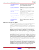
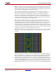
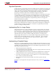
While the multiply-accumulate function supported by a Virtex®-4 DSP block is familiar to
a DSP engineer, it is instructive to take a closer look at the Virtex® FPGA family logic slice
(shown below), which is the fundamental unit of the logic fabric array.
Each logic slice contains two 4-input lookup tables (LUTs), two configurable D-flip flops,
multiplexers, dedicated carry logic, and gates used for creating slice-based multipliers.
Each LUT can implement an arbitrary 4-input Boolean function. Coupled with dedicated
logic for implementing fast carry circuits, the LUTs can also be used to build fast
adder/subtractors and multipliers of essentially any word size. In addition to
implementing Boolean functions, each LUT can also be configured as a 16x1 bit RAM or as
a shift register (SRL16). An SRL16 shift register is a synchronously clocked 16x1 bit delay
line with a dynamically addressable tap point.
In System Generator, these different memory options are represented with higher-level
abstractions. Instead of providing a D-flip flop primitive, System Generator provides a
register of arbitrary size. There are two blocks that provide abstractions of arbitrary
width, arbitrary depth delay lines that map directly onto the SRL16 configuration. The
delay block can be used for pipeline balancing, and can also be used as storage for time-