
User guide

System Generator for DSP User Guide www.xilinx.com 155
UG640 (v 12.2) July 23, 2010
Integrating a Processor with Custom Logic
In hardware co-simulation, the processor subsystem is driven by the board clock directly.
This means that the processor subsystem must be able to meet the requirements set by this
clock. In hardware co-simulation, it is possible for users to select different ratios of clock
frequencies based of the input board frequency. Note that this hardware co-simulation
clock is generated in the hardware co-simulation module and is not available to the
processor subsystem.
For exmaple, if the input board frequency is 125MHz, and the hardware co-simulation
frequency is set to 33 Mhz, only the custom logic portion of the design will be constrained
to 33 MHz, the MicroBlaze processor must still run at 125 MHz. If the MicroBlaze processor
cannot meet timing at this speed, you need to instantiate a clock generator pheripheral in
your XPS project and slow down the clock in that way.
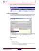
Clock Wiring in the Hardware Co-Simulation Flow
When a Xilinx Platform Studio (XPS) project is imported into System Generator using the
EDK Processor block, you can generate a Hardware Co-Simulation block for the imported
XPS project. The Hardware Co-Simulation block allows you to run the XPS system on the
hardware while simulating the System Generator design in Simulink on the host PC.
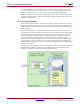
In a typical hardware co-simulation session, a portion of the System Generator design runs
on hardware, while the rest of the design is simulated in software. The design portion
running in hardware is driven with a clock generated by a clock control module. This clock
control module is a piece of hardware automatically inserted by System Generator
hardware co-simulation to ensure that the hardware and the Simulink simulation are
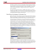
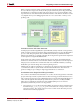
synchronized. The hardware co-simulation flow allows you to select the clock frequency
used to drive the hardware. For example, in the hardware co-simulation settings dialog
box for the ML506 board shown below, a 100 MHz clock frequency is selected. The Design
Under Test (DUT) running on hardware is then driven by a 100 MHz clock output from the
hardware co-simulation clock control module.
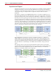
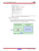
When participating in hardware co-simulation, the EDK Processor block provides two
clocking schemes to suit different simulation and runtime requirements: dual-clock wiring
and single-clock wiring. In dual-clock wiring, the EDK Processor and the System Generator
design are driven by two asynchronous clocks; in single-clock wiring, the EDK Processor
and the rest of the System Generator design are driven by the same clock.