
User guide


System Generator for DSP User Guide www.xilinx.com 145
UG640 (v 12.2) July 23, 2010
Integrating a Processor with Custom Logic
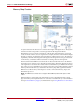
The EDK Processor block provides a solution to both these problems through automation.
The EDK Processor block encourages the interface between the processor and the custom
logic to be specified via shared-memories. Shared-memories are used to provide storage
locations that can be referenced by name. This allows a memory map and the associated
software drivers to be generated.
Please refer to the EDK Processor
block documentation regarding information on the use
of the block. The topics that follow describe the automatic memory map creation,
hardware generation in different compilation flows, and the use of the associated software
drivers, and the two clock wiring schemes provided by the EDK Processor block.
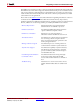
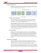
Memory Map Creation Explains the memory map generated when
shared memories are added to a processor.
Hardware Generation Documents the different hardware generation
options in different compilation flows.
Hardware Co-Simulation Explains how to create a hardware co-
simulation model for the EDK Processor block.
The Software Driver Documents how a software driver is created and
how to writing software using the software
driver to perform read/write operations to the
memory-mapped interface.
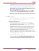
Writing a Software Program Documents the process of writing software to
control hardware created in System Generator.
Asynchronous Support Documents the capability in System Generator,
in both import and export mode, to allow the
processor and the System Generator design to
run with different clocks.
Clock Wiring in the Hardware
Co-Simulation Flow
Documents the dual clock wiring and single
clock wiring scheme offered by the EDK
Processor block in the hardware co-simulation
flow.
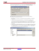
Troubleshooting Describes how to resolve issues such as how to
update outdated netlists that are cashed inside
XPS.