
User guide

132 www.xilinx.com System Generator for DSP User Guide
UG640 (v 12.2) July 23, 2010
Chapter 1: Hardware Design Using System Generator
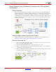
5. Integrate ChipScope into the Simulink model. The ChipScope block can be found in
the Simulink Library Browser in the Xilinx Blockset, under the Tools library. While
holding down the left mouse button, select the ChipScope block and drag it into the
open area in the lower-right corner of the Simulink model.
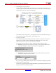
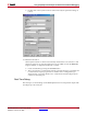
6. Double click on the ChipScope block in order to set the following parameters:
♦ Number of trigger ports: Multiple trigger ports allow a larger range of events to
be detected and can reduce the number of values that must be stored. Up to 16
trigger ports can be selected. In this example, only one is used.
♦ Display settings for trigger port: For each trigger port, the number of match units
and the match type need to be set. The pulldown menu displays options for a
particular trigger port. For N ports, the display options for trigger port 0 to N-1
can be shown. In this example, there is one Trigger port named Trig0. This option
should therefore be set to 0.
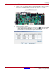
♦ Number of match units: Using multiple match units per trigger port increases the
flexibility of event detection. One to four match units can be used in conjunction
to test for a trigger event. In this example, this option should be set to 1 since you
are only checking for one condition (i.e., the 8-bit counter value). You will set the
trigger value at run-time in the ChipScope Pro Analyzer.
♦ Match type: This option can be set to one of the following six types:
1. Basic: performs = or <> comparisons
2. Basic With Edges: in addition to the basic operations high/low, low/high
transitions can also be detected
3. Extended: performs =, <>,>,<, <=, >= comparisons
4. Extended With Edges: in addition to the extended operations, high/low,
low/high transitions can also be detected.
5. Range: performs =, <>, >, >=, <, <=, in range, not in range comparisons
6. Range With Edges: in addition to the range operations, high/low, low/high
transitions can also be detected. In this example, set the Match Type to Basic with
Edges.
♦ Number of data ports: Up to 256 bits can be captured per sample. This means that
the sum over all ports of the bits used per port must be less than or equal to 256.
System Generator propagates the data width automatically; therefore, only the
number of data ports needs to be specified. In this example, you want to view the
sine and cosine and trig_counter, hence you enter 3.
♦ Depth of capture buffer: The depth of the capture buffer is a power of 2, up to
16384 samples. In this example, set the depth to 1024 (min value required for V5).