
User guide

System Generator for DSP User Guide www.xilinx.com 125
UG640 (v 12.2) July 23, 2010
Generating Multiple Cycle-True Islands for Distinct Clocks
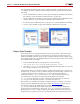
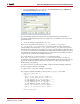
8. Press the Generate button. You may leave the Part, Synthesis Tool, and Hardware
Description Language fields as they are.
Once the Multiple Subsystem Generator block is finished running, it will display a
message box indicating that generation is complete. It is worthwhile to take a look at the
generated results.
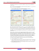
9. cd into the design's target directory, netlist.
There are two NGC files in this directory: ss_clk_domaina_cw.ngc and
ss_clk_domainb_cw.ngc. These files store the netlist and constraints information
corresponding to the subsystems ss_clk_domaina and ss_clk_domainb. Note that
these NGC files include the clock wrapper layer logic associated with each subsystem. This
is necessary to ensure that any clock enable logic required by a multirate design is included
in netlist file. By using the clock wrapper layer of a design, the corresponding clock driver
components are automatically included in the netlist.
Also in this directory is a dual port memory core netlist file named
dual_port_block_memory_virtex2_6_1_ef64ec122427b7be.edn. This core
provides the hardware implementation for the Shared Memory blocks used in the original
design. The width and depth of the memory are based on values used in the Shared
Memory block configurations.
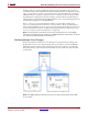
You will now take a look at the top-level HDL component that the Multiple Subsystem
Generator block produced for the design.
10. Open the two_async_clks.vhd file in a text editor.
This component defines the HDL top-level for the two_async_clks model.
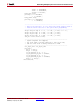
entity two_async_clks is
port (
din_a: in std_logic_vector(7 downto 0);
din_b: in std_logic_vector(7 downto 0);
ss_clk_domaina_cw_ce: in std_logic := '1';
ss_clk_domaina_cw_clk: in std_logic;
ss_clk_domainb_cw_ce: in std_logic := '1';
ss_clk_domainb_cw_clk: in std_logic;
dout_a: out std_logic_vector(7 downto 0);
dout_b: out std_logic_vector(7 downto 0)
);
end two_async_clks;