
User guide

System Generator for DSP User Guide www.xilinx.com 123
UG640 (v 12.2) July 23, 2010
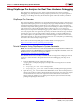
Generating Multiple Cycle-True Islands for Distinct Clocks
This is because the connection is implicitly defined by the fact that the two Shared Memory
blocks specify the same shared memory object name and therefore, share an address space.
When the two subsystems are wired together and translated into hardware, the shared
memory blocks are moved from their respective subsystems and merged into a block RAM
core. For more information on how this works, refer to the topic Multiple Subsystem
Generator.
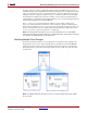
The synchronous islands sample different input sources. Island ss_clk_domainA samples a
sinusoid input, while ss_clk_domainB samples a saw-tooth wave input. Each subsystem
writes its samples into opposite halves of the shared memory. Once an island has filled its
half of memory, it reads samples from the other island's half. You can simulate the design
to visualize of the model's behavior.
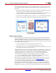
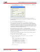
3. Press the Simulink Start button to simulate the design.
4. Open the scope to visualize the output signals.
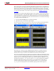
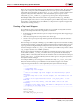
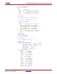
Also shown in the output scope are the two clocks, clk_A and clk_B. At the default time
scale, it is difficult to distinguish the two. Zoom in to get a more detailed view.
Notice that clk_A and clk_B have different periods and are out of phase with one
another. Earlier, it was claimed that System Generator uses a single clock source per
design. In the scope, you clearly see two different clocks. How is this possible?
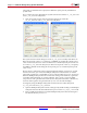
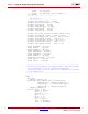
The answer is in the hierarchical construction of the design. All blocks are buried in at least
one level of hierarchy using subsystems. Because there is no System Generator block at the
top level, you can consider each subsystem as a completely separate System Generator
design (at least for the time being). In this model, you have effectively defined two clock
domains by giving the ss_clk_domainA and ss_clk_domainB subsystems different
Simulink system periods. This is allowed since you are treating these subsystems as
separate System Generator designs. The clock probes in the ss_clk_domainA and
ss_clk_domainB subsystems use the Simulink system periods in their respective