
User guide

106 www.xilinx.com System Generator for DSP User Guide
UG640 (v 12.2) July 23, 2010
Chapter 1: Hardware Design Using System Generator
You can find the above complete model at the following pathname:
<sysgen_path>/examples/dsp48/mult35x35/dsp48macro_mult35x35.mdl
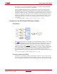
DSP48 Design Techniques
Designing Filters with the DSP48
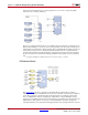
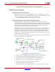
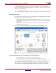
The DSP48 is an ideal block to implement FIR filters. You can examine how to use the
DSP48 block for Type 1 and Type 2 FIR filters by opening the simulink model that is located
at the follwing pathname in the System Generator software tree:
.../sysgen/examples/dsp48/firs/dsp48_firs_tb.mdl
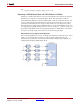
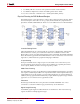
Design Techniques for Very-High Performance Designs
DSP48-based designs usually require I/O, BRAMS and SLICE logic. Typically, this
associated SLICE logic is used to implement delay registers, SRL16s, muxes, counters, and
control logic. Since the DSP48 block is expected to operate at speeds greater than 500 MHz,
other components will also be required to operate at the same speed. This generally
requires special design techniques for the non-DSP48 logic.
At 500 MHz only 2 ns is available in each clock. For V4-11 devices, roughly 300 ps are
required for register clock to out and 300 ps for setup. For comparison, a LUT delay is 166
ps. Special inputs and outputs such as clock enables and DSP48 and BRAM signals
generally have setup and clock to out times closer to 500 ps. With clock skew and jitter,
roughly 1 ns is available for net delays. This restriction will generally allow only 1 net in
each path and it must be fairly short.
There are a number of guidelines that can be used to insure the operation at DSP48 speeds.
Some of these guidelines are outlined below.
1. Always use DSP48, BRAM16, FIFO16 with input, mult and output registers
2. Use additional FF to buffer DSP48 and BRAM outputs if necessary
3. Plan out the usage of the PCOUT-PCIN bus to allow DSP48 chaining
4. Add registers to any path that is greater than 20 - 40 slices long
5. Limit fanout to 32 loads located within a 20 slice distance
6. Add output registers to any LUT-based logic
7. Limit LUTs to 1 level or a 4:1 MUX and insure a local register for input or output