
User`s guide
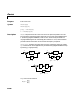
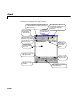
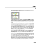
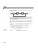
Table Of Contents
- Preface
- Quick Start
- LTI Models
- Introduction
- Creating LTI Models
- LTI Properties
- Model Conversion
- Time Delays
- Simulink Block for LTI Systems
- References
- Operations on LTI Models
- Arrays of LTI Models
- Model Analysis Tools
- The LTI Viewer
- Introduction
- Getting Started Using the LTI Viewer: An Example
- The LTI Viewer Menus
- The Right-Click Menus
- The LTI Viewer Tools Menu
- Simulink LTI Viewer
- Control Design Tools
- The Root Locus Design GUI
- Introduction
- A Servomechanism Example
- Controller Design Using the Root Locus Design GUI
- Additional Root Locus Design GUI Features
- References
- Design Case Studies
- Reliable Computations
- Reference
- Category Tables
- acker
- append
- augstate
- balreal
- bode
- c2d
- canon
- care
- chgunits
- connect
- covar
- ctrb
- ctrbf
- d2c
- d2d
- damp
- dare
- dcgain
- delay2z
- dlqr
- dlyap
- drmodel, drss
- dsort
- dss
- dssdata
- esort
- estim
- evalfr
- feedback
- filt
- frd
- frdata
- freqresp
- gensig
- get
- gram
- hasdelay
- impulse
- initial
- inv
- isct, isdt
- isempty
- isproper
- issiso
- kalman
- kalmd
- lft
- lqgreg
- lqr
- lqrd
- lqry
- lsim
- ltiview
- lyap
- margin
- minreal
- modred
- ndims
- ngrid
- nichols
- norm
- nyquist
- obsv
- obsvf
- ord2
- pade
- parallel
- place
- pole
- pzmap
- reg
- reshape
- rlocfind
- rlocus
- rltool
- rmodel, rss
- series
- set
- sgrid
- sigma
- size
- sminreal
- ss
- ss2ss
- ssbal
- ssdata
- stack
- step
- tf
- tfdata
- totaldelay
- zero
- zgrid
- zpk
- zpkdata
- Index
rltool
11-187
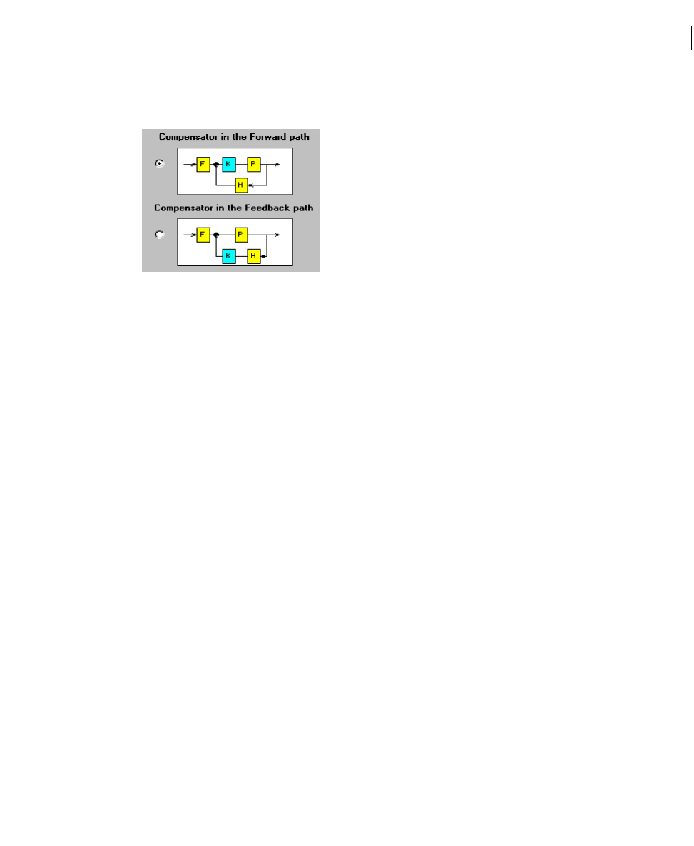
This tool can be applied to S ISO LTI systems whose feedback structure is in
one of the following two configurations.
In either configuration,
F is a pre-filter, P is the plant model, H is the sensor
dynamics,a nd
K is the compensator to be designed. In terms of the GUI design
procedure, once you specify them,
F, P,andHare fixed in the feedback
structure. This tr iple, along with the feedback structure, is called the design
model.
A design model can be constructed for the GUI by selecting the
Import Model
menu item from the File menu of the Root Locus Design GUI. Once you select
the item, the
Import Design Model window opens. You can then import SISO
LTI models that have been created with
ss, tf,orzpk in your workspace or on
yourdisk(or SISOLTIblockscontainedinopen orsavedSimulink models)i nto
F,P,andH. Otherwise, youcanspecifyyourdesignmodelbydefiningF, P,and
Hmanually with L TI models created using ss, tf,orzpk in the text boxes
provided on the
Import Design Model window.
If sys is any SISO LTI object (created with ss, tf,orzpk)thatexistsinthe
MATLAB workspace,
rltool(sys) initializes a Root Locus Design GUI, by
setting the plant model
P to sys.
rltool(sys,comp) also initializes aRoot LocusDesignGUIfortheplantmodel
sys. In addition, the root locus compensator is initialized to comp,wherecomp
is any SISO LTI object that exists in the MATLAB workspace.
When either the plant, or both the plant and the compensator are provided as
arguments to
rltool, the root locus of the closed-loop poles and their locations
forthecurrent compensatorgain aredrawn onthe RootLocusDesignG UI. The
closed-loop model is generated by placing the compensator (
comp)andplant