
User`s guide

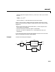

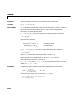
Table Of Contents
- Preface
- Quick Start
- LTI Models
- Introduction
- Creating LTI Models
- LTI Properties
- Model Conversion
- Time Delays
- Simulink Block for LTI Systems
- References
- Operations on LTI Models
- Arrays of LTI Models
- Model Analysis Tools
- The LTI Viewer
- Introduction
- Getting Started Using the LTI Viewer: An Example
- The LTI Viewer Menus
- The Right-Click Menus
- The LTI Viewer Tools Menu
- Simulink LTI Viewer
- Control Design Tools
- The Root Locus Design GUI
- Introduction
- A Servomechanism Example
- Controller Design Using the Root Locus Design GUI
- Additional Root Locus Design GUI Features
- References
- Design Case Studies
- Reliable Computations
- Reference
- Category Tables
- acker
- append
- augstate
- balreal
- bode
- c2d
- canon
- care
- chgunits
- connect
- covar
- ctrb
- ctrbf
- d2c
- d2d
- damp
- dare
- dcgain
- delay2z
- dlqr
- dlyap
- drmodel, drss
- dsort
- dss
- dssdata
- esort
- estim
- evalfr
- feedback
- filt
- frd
- frdata
- freqresp
- gensig
- get
- gram
- hasdelay
- impulse
- initial
- inv
- isct, isdt
- isempty
- isproper
- issiso
- kalman
- kalmd
- lft
- lqgreg
- lqr
- lqrd
- lqry
- lsim
- ltiview
- lyap
- margin
- minreal
- modred
- ndims
- ngrid
- nichols
- norm
- nyquist
- obsv
- obsvf
- ord2
- pade
- parallel
- place
- pole
- pzmap
- reg
- reshape
- rlocfind
- rlocus
- rltool
- rmodel, rss
- series
- set
- sgrid
- sigma
- size
- sminreal
- ss
- ss2ss
- ssbal
- ssdata
- stack
- step
- tf
- tfdata
- totaldelay
- zero
- zgrid
- zpk
- zpkdata
- Index
connect
11-35
externaloutputsare outputs2 and7 of sys,theninputs and outputs should
be set to
inputs = [1 2 15];
outputs = [2 7];
The final model sysc has these particular inputs and outputs.
Since it is easy to make a mistake entering all the data required for a large
model, be sure to verify your model in as many ways as you can. Here are some
suggestions:
• Make sure the poles of the unconnected model
sys matchthepolesofthe
various blocks in the diagram.
• Check that the final poles and DC gains are reasonable.
• Plot the
step and bode responses of sysc and compare them with your
expectations.
Ifyou needto workextensivelywithblock diagrams, Simulinkisa much easier
and more comprehensive tool for model building.
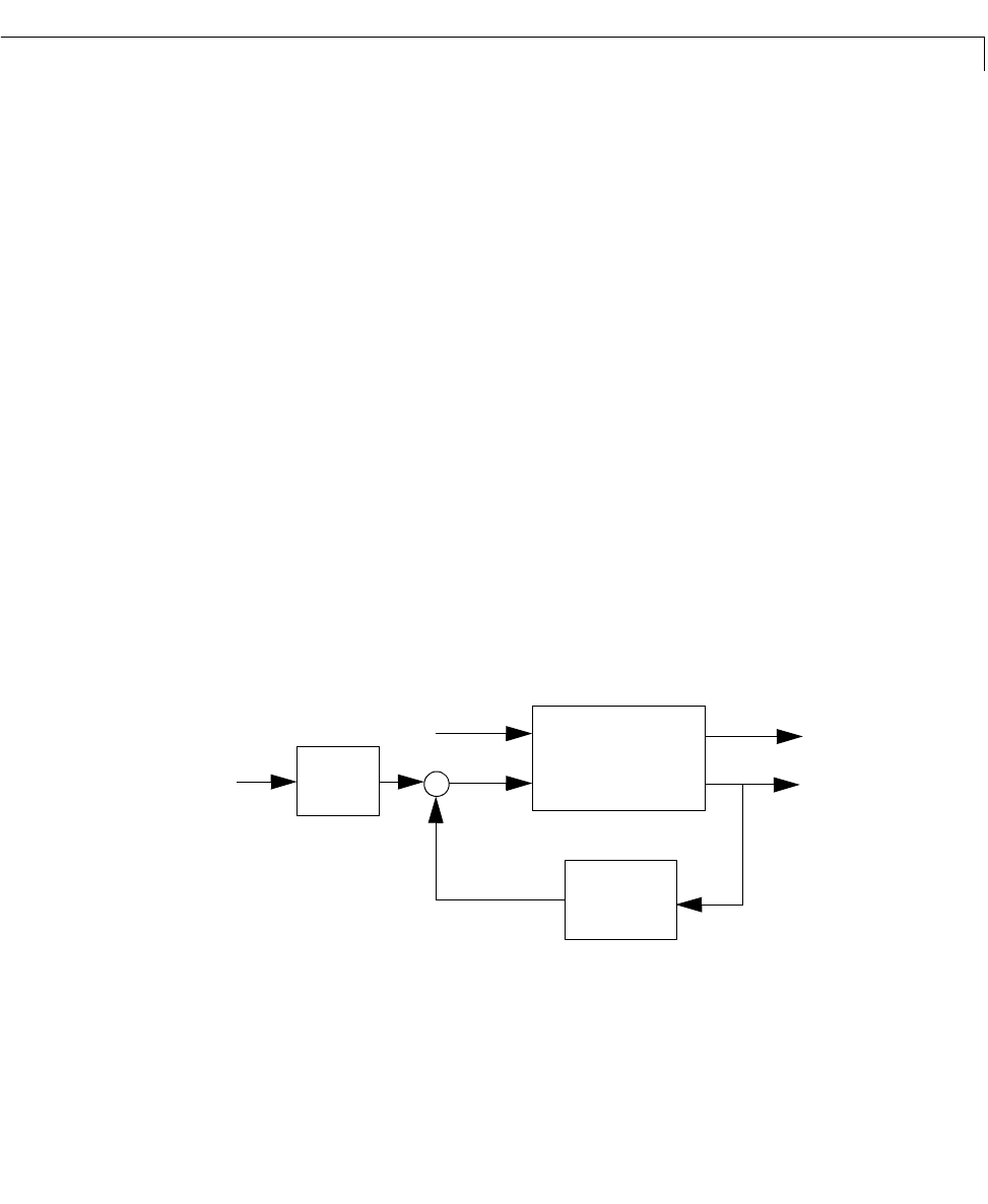
Example Consider the following block diagram
x
·
Ax Bu+=
yCxDu+=
2s1+()
s2+
--------------------
10
s 5+
------------
y
1
y
2
u
2
u
1
u
c
sys1
sys2
sys3
+
–