
User`s guide
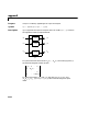
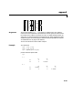
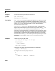
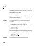
Table Of Contents
- Preface
- Quick Start
- LTI Models
- Introduction
- Creating LTI Models
- LTI Properties
- Model Conversion
- Time Delays
- Simulink Block for LTI Systems
- References
- Operations on LTI Models
- Arrays of LTI Models
- Model Analysis Tools
- The LTI Viewer
- Introduction
- Getting Started Using the LTI Viewer: An Example
- The LTI Viewer Menus
- The Right-Click Menus
- The LTI Viewer Tools Menu
- Simulink LTI Viewer
- Control Design Tools
- The Root Locus Design GUI
- Introduction
- A Servomechanism Example
- Controller Design Using the Root Locus Design GUI
- Additional Root Locus Design GUI Features
- References
- Design Case Studies
- Reliable Computations
- Reference
- Category Tables
- acker
- append
- augstate
- balreal
- bode
- c2d
- canon
- care
- chgunits
- connect
- covar
- ctrb
- ctrbf
- d2c
- d2d
- damp
- dare
- dcgain
- delay2z
- dlqr
- dlyap
- drmodel, drss
- dsort
- dss
- dssdata
- esort
- estim
- evalfr
- feedback
- filt
- frd
- frdata
- freqresp
- gensig
- get
- gram
- hasdelay
- impulse
- initial
- inv
- isct, isdt
- isempty
- isproper
- issiso
- kalman
- kalmd
- lft
- lqgreg
- lqr
- lqrd
- lqry
- lsim
- ltiview
- lyap
- margin
- minreal
- modred
- ndims
- ngrid
- nichols
- norm
- nyquist
- obsv
- obsvf
- ord2
- pade
- parallel
- place
- pole
- pzmap
- reg
- reshape
- rlocfind
- rlocus
- rltool
- rmodel, rss
- series
- set
- sgrid
- sigma
- size
- sminreal
- ss
- ss2ss
- ssbal
- ssdata
- stack
- step
- tf
- tfdata
- totaldelay
- zero
- zgrid
- zpk
- zpkdata
- Index

bode
11-20
uses red dashed lines for the first system sys1 and green 'x' markers for the
second system
sys2.
When invoked w ith left-hand arguments
[mag,phase,w] = bode(sys)
[mag,phase] = bode(sys,w)
return the magnitude and phase (in degrees) of the frequency response at the
frequencies
w (in rad/sec). The outputs mag and phase are 3-D arrays with the
frequency as t he last dimension (see “Arguments” below for details). You can
convert the magnitude to decibels by
magdb = 20*log10(mag)
Remark If sys is an FRD model, bode(sys,w), w can only include frequencies in
sys.frequency.
Arguments The output arguments mag and phase a re 3-D arrays with dimensions
For SISO systems,
mag(1,1,k) and phase(1,1,k) give the magnitude and
phase of the response at the frequency =
w(k).
MIMO systems are treated as arrays of SISO systems and the magnitudes and
phases are computedforeach SISO entry independently( isthetransfer
function from input to output ). The values
mag(i,j,k) and phase(i,j,k)
then characterize the response of at the frequency w(k).
Example You can plot the Bode response o f the continuous SISO system
number of outputs
()
number of inputs
()×
length of
w()×
ω
k
mag(1,1,k) hjω
k
()=
phase(1,1,k) hjω
k
()∠=
h
ij
h
ij
j
i
h
ij
mag(i,j,k) h
ij
jω
k
()=
phase(i,j,k) h
ij
jω
k
()∠=