
User`s guide
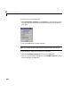
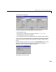
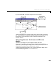
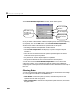

Table Of Contents
- Preface
- Quick Start
- LTI Models
- Introduction
- Creating LTI Models
- LTI Properties
- Model Conversion
- Time Delays
- Simulink Block for LTI Systems
- References
- Operations on LTI Models
- Arrays of LTI Models
- Model Analysis Tools
- The LTI Viewer
- Introduction
- Getting Started Using the LTI Viewer: An Example
- The LTI Viewer Menus
- The Right-Click Menus
- The LTI Viewer Tools Menu
- Simulink LTI Viewer
- Control Design Tools
- The Root Locus Design GUI
- Introduction
- A Servomechanism Example
- Controller Design Using the Root Locus Design GUI
- Additional Root Locus Design GUI Features
- References
- Design Case Studies
- Reliable Computations
- Reference
- Category Tables
- acker
- append
- augstate
- balreal
- bode
- c2d
- canon
- care
- chgunits
- connect
- covar
- ctrb
- ctrbf
- d2c
- d2d
- damp
- dare
- dcgain
- delay2z
- dlqr
- dlyap
- drmodel, drss
- dsort
- dss
- dssdata
- esort
- estim
- evalfr
- feedback
- filt
- frd
- frdata
- freqresp
- gensig
- get
- gram
- hasdelay
- impulse
- initial
- inv
- isct, isdt
- isempty
- isproper
- issiso
- kalman
- kalmd
- lft
- lqgreg
- lqr
- lqrd
- lqry
- lsim
- ltiview
- lyap
- margin
- minreal
- modred
- ndims
- ngrid
- nichols
- norm
- nyquist
- obsv
- obsvf
- ord2
- pade
- parallel
- place
- pole
- pzmap
- reg
- reshape
- rlocfind
- rlocus
- rltool
- rmodel, rss
- series
- set
- sgrid
- sigma
- size
- sminreal
- ss
- ss2ss
- ssbal
- ssdata
- stack
- step
- tf
- tfdata
- totaldelay
- zero
- zgrid
- zpk
- zpkdata
- Index

Additional Root Locus Design GUI Features
8-41
Erasing Compensator Poles and Zeros
You ca n delete any co m p ens ator poles and zeros in o ne of two ways:
• Check t he associated
Delete box on the Edit Compensator... window
obtained from the
Tools menu.
• Click on the erase button (fourth from lef t on the root locus toolbar) and click
on the pole or zero to delete.
After us ing the roo t locus toolbar erase button to dele te a pole o r ze ro, the
following occurs:
• The erase button pops up a nd the default drag mode is restored.
• The zer o or po le you erased (a nd, if ap plicable, its conjug ate) is remove d from
the root locus and from the
Current Compensator text.
• The root locus plot and any linked LTI Viewer response plots are
recalculated.
Listing Poles and Zeros
At any point when the Root Locus Design GUI is open, you can view:
• The closed-loop pole locations associated with the current
Gain setting
• The poles, zeros, and gain of each design model component