
User`s guide
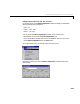
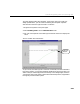
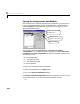
Table Of Contents
- Preface
- Quick Start
- LTI Models
- Introduction
- Creating LTI Models
- LTI Properties
- Model Conversion
- Time Delays
- Simulink Block for LTI Systems
- References
- Operations on LTI Models
- Arrays of LTI Models
- Model Analysis Tools
- The LTI Viewer
- Introduction
- Getting Started Using the LTI Viewer: An Example
- The LTI Viewer Menus
- The Right-Click Menus
- The LTI Viewer Tools Menu
- Simulink LTI Viewer
- Control Design Tools
- The Root Locus Design GUI
- Introduction
- A Servomechanism Example
- Controller Design Using the Root Locus Design GUI
- Additional Root Locus Design GUI Features
- References
- Design Case Studies
- Reliable Computations
- Reference
- Category Tables
- acker
- append
- augstate
- balreal
- bode
- c2d
- canon
- care
- chgunits
- connect
- covar
- ctrb
- ctrbf
- d2c
- d2d
- damp
- dare
- dcgain
- delay2z
- dlqr
- dlyap
- drmodel, drss
- dsort
- dss
- dssdata
- esort
- estim
- evalfr
- feedback
- filt
- frd
- frdata
- freqresp
- gensig
- get
- gram
- hasdelay
- impulse
- initial
- inv
- isct, isdt
- isempty
- isproper
- issiso
- kalman
- kalmd
- lft
- lqgreg
- lqr
- lqrd
- lqry
- lsim
- ltiview
- lyap
- margin
- minreal
- modred
- ndims
- ngrid
- nichols
- norm
- nyquist
- obsv
- obsvf
- ord2
- pade
- parallel
- place
- pole
- pzmap
- reg
- reshape
- rlocfind
- rlocus
- rltool
- rmodel, rss
- series
- set
- sgrid
- sigma
- size
- sminreal
- ss
- ss2ss
- ssbal
- ssdata
- stack
- step
- tf
- tfdata
- totaldelay
- zero
- zgrid
- zpk
- zpkdata
- Index

8 The Root Locus Design GUI
8-38
Additional Root Locus Design GUI Features
This section describes several features of the Root Locus Design GUI not
covered in the servome chanism example. These are listed as follows:
• Specifying design models: general concepts:
- Creating models manually within the GUI
- Designating the model source
• Getting help with the Root Locus Design GUI
• Erasing compensator poles and zeros
• Listing poles and zeros
• Printing the root locus
• Drawing a Simulink diagram of the closed-loop model
• Converting between continuous and discrete models
• Clearing data
Specifying Design Models: General Concepts
In this section we provide general concepts for specifying the design model by
using one or bo th of the following methods:
• Creating models ma nually wit hin the G UI
• Designating the model source:
- The MATLAB workspace
- A MA T- file
- An open or saved Simulink model
Creating Models Manually Within the GUI
You can create models for root locus analysis manually in the Import LTI
Design Model
window using tf, ss,orzpk. To do so, just edit the text boxes
next to
P, F,orHusing any of these MATLAB expressions. You can also use a
scalar number to specify
P, F,orH.