
User`s guide
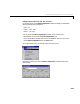
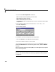
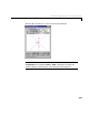
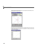
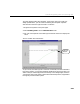
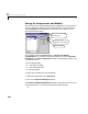
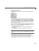
Table Of Contents
- Preface
- Quick Start
- LTI Models
- Introduction
- Creating LTI Models
- LTI Properties
- Model Conversion
- Time Delays
- Simulink Block for LTI Systems
- References
- Operations on LTI Models
- Arrays of LTI Models
- Model Analysis Tools
- The LTI Viewer
- Introduction
- Getting Started Using the LTI Viewer: An Example
- The LTI Viewer Menus
- The Right-Click Menus
- The LTI Viewer Tools Menu
- Simulink LTI Viewer
- Control Design Tools
- The Root Locus Design GUI
- Introduction
- A Servomechanism Example
- Controller Design Using the Root Locus Design GUI
- Additional Root Locus Design GUI Features
- References
- Design Case Studies
- Reliable Computations
- Reference
- Category Tables
- acker
- append
- augstate
- balreal
- bode
- c2d
- canon
- care
- chgunits
- connect
- covar
- ctrb
- ctrbf
- d2c
- d2d
- damp
- dare
- dcgain
- delay2z
- dlqr
- dlyap
- drmodel, drss
- dsort
- dss
- dssdata
- esort
- estim
- evalfr
- feedback
- filt
- frd
- frdata
- freqresp
- gensig
- get
- gram
- hasdelay
- impulse
- initial
- inv
- isct, isdt
- isempty
- isproper
- issiso
- kalman
- kalmd
- lft
- lqgreg
- lqr
- lqrd
- lqry
- lsim
- ltiview
- lyap
- margin
- minreal
- modred
- ndims
- ngrid
- nichols
- norm
- nyquist
- obsv
- obsvf
- ord2
- pade
- parallel
- place
- pole
- pzmap
- reg
- reshape
- rlocfind
- rlocus
- rltool
- rmodel, rss
- series
- set
- sgrid
- sigma
- size
- sminreal
- ss
- ss2ss
- ssbal
- ssdata
- stack
- step
- tf
- tfdata
- totaldelay
- zero
- zgrid
- zpk
- zpkdata
- Index
8 The Root Locus Design GUI
8-32
You can use the Edit Compensator window to:
• Edit the locations of compensator poles and zeros.
• Add compensator poles and zeros.
• Delete compensator poles and zeros.
• Change the name of the compensator (This name is usedwhen exporting the
compensator).
For this e xample, edit the poles and zeros t o be at
and
respectively.
Your GUI looks like this.
If, in addition, you want to add poles to the compensator:
1 Click on Add Pole. A new editable text field appears.
2 Enter the new pole location in the text field.
The procedure is the same for adding zeros, only use the
Add Zero button in
place of the
Add Pole button. To erase any poles or zeros, select the Delete
checkbox.
Beforeclosingthiswindowbyselecting
OK, you can also optionally change the
name of the compensator.
Note: You can also erase poles or zeros on the root locus using the erase
button on the root locus toolbar. See “Erasing Compensator Poles and Zeros”
on page 8-41
110
–
140i,
±
70
–
270 i,
±