
User`s guide
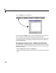
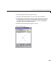
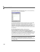
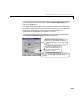
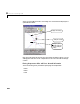
Table Of Contents
- Preface
- Quick Start
- LTI Models
- Introduction
- Creating LTI Models
- LTI Properties
- Model Conversion
- Time Delays
- Simulink Block for LTI Systems
- References
- Operations on LTI Models
- Arrays of LTI Models
- Model Analysis Tools
- The LTI Viewer
- Introduction
- Getting Started Using the LTI Viewer: An Example
- The LTI Viewer Menus
- The Right-Click Menus
- The LTI Viewer Tools Menu
- Simulink LTI Viewer
- Control Design Tools
- The Root Locus Design GUI
- Introduction
- A Servomechanism Example
- Controller Design Using the Root Locus Design GUI
- Additional Root Locus Design GUI Features
- References
- Design Case Studies
- Reliable Computations
- Reference
- Category Tables
- acker
- append
- augstate
- balreal
- bode
- c2d
- canon
- care
- chgunits
- connect
- covar
- ctrb
- ctrbf
- d2c
- d2d
- damp
- dare
- dcgain
- delay2z
- dlqr
- dlyap
- drmodel, drss
- dsort
- dss
- dssdata
- esort
- estim
- evalfr
- feedback
- filt
- frd
- frdata
- freqresp
- gensig
- get
- gram
- hasdelay
- impulse
- initial
- inv
- isct, isdt
- isempty
- isproper
- issiso
- kalman
- kalmd
- lft
- lqgreg
- lqr
- lqrd
- lqry
- lsim
- ltiview
- lyap
- margin
- minreal
- modred
- ndims
- ngrid
- nichols
- norm
- nyquist
- obsv
- obsvf
- ord2
- pade
- parallel
- place
- pole
- pzmap
- reg
- reshape
- rlocfind
- rlocus
- rltool
- rmodel, rss
- series
- set
- sgrid
- sigma
- size
- sminreal
- ss
- ss2ss
- ssbal
- ssdata
- stack
- step
- tf
- tfdata
- totaldelay
- zero
- zgrid
- zpk
- zpkdata
- Index
Controller Design Using the Root Locus Design GUI
8-27
Once you have the gain specified, you can add poles or zeros to the
compensator.Youcan addpolesandzerostothecompensator(orremovethem)
in two ways:
• Use b uttons on the root locus toolbar section of the GUI for pole/zero
placement.
• Use the
Edit Compensator menu item on the Tools menu.
The root locus toolbar is convenient for graphically placing compensator poles
and zeros so that you meet the design specifications for a given gain set point.
This method may require a certain amount of trial and error.
You can use the
Edit Compensator menu item to:
• Fine-tune compensator parameter values for design implementation.
• Revise or implement an existing compensator design.
For this example we first use the root locus toolbar to place compensator poles
and zeros on the root locus, and then use the
Edit Compensator menu item to
set the compensator pole and zero locations for a specific compensatorsolution.
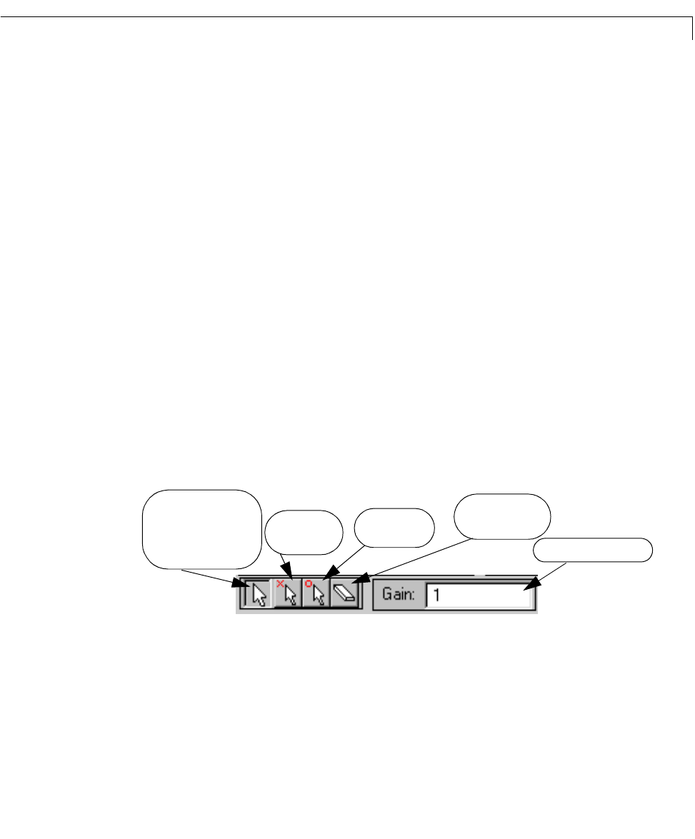
Placing Compensator Poles and Zeros Using the Root Locus Toolbar
The root locus toolbar is located on the left side of the GUI, above the plot
region. The figure below describes the root locus toolbar buttons.
Drag compensator poles
and zeros and closed-loop
Operate in default mode:
Add compensator
poles.
Add compensator
zeros.
Erase compensator
poles/zeros.
Edit the compensator gain.
poles.