
User`s guide
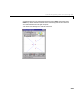
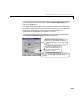
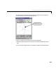
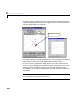
Table Of Contents
- Preface
- Quick Start
- LTI Models
- Introduction
- Creating LTI Models
- LTI Properties
- Model Conversion
- Time Delays
- Simulink Block for LTI Systems
- References
- Operations on LTI Models
- Arrays of LTI Models
- Model Analysis Tools
- The LTI Viewer
- Introduction
- Getting Started Using the LTI Viewer: An Example
- The LTI Viewer Menus
- The Right-Click Menus
- The LTI Viewer Tools Menu
- Simulink LTI Viewer
- Control Design Tools
- The Root Locus Design GUI
- Introduction
- A Servomechanism Example
- Controller Design Using the Root Locus Design GUI
- Additional Root Locus Design GUI Features
- References
- Design Case Studies
- Reliable Computations
- Reference
- Category Tables
- acker
- append
- augstate
- balreal
- bode
- c2d
- canon
- care
- chgunits
- connect
- covar
- ctrb
- ctrbf
- d2c
- d2d
- damp
- dare
- dcgain
- delay2z
- dlqr
- dlyap
- drmodel, drss
- dsort
- dss
- dssdata
- esort
- estim
- evalfr
- feedback
- filt
- frd
- frdata
- freqresp
- gensig
- get
- gram
- hasdelay
- impulse
- initial
- inv
- isct, isdt
- isempty
- isproper
- issiso
- kalman
- kalmd
- lft
- lqgreg
- lqr
- lqrd
- lqry
- lsim
- ltiview
- lyap
- margin
- minreal
- modred
- ndims
- ngrid
- nichols
- norm
- nyquist
- obsv
- obsvf
- ord2
- pade
- parallel
- place
- pole
- pzmap
- reg
- reshape
- rlocfind
- rlocus
- rltool
- rmodel, rss
- series
- set
- sgrid
- sigma
- size
- sminreal
- ss
- ss2ss
- ssbal
- ssdata
- stack
- step
- tf
- tfdata
- totaldelay
- zero
- zgrid
- zpk
- zpkdata
- Index
Controller Design Using the Root Locus Design GUI
8-25
Let’s place approximate design region bo undaries on our root locus plot based
on our design specifications. To do so, select the
Add Grid/Boundary menu
item in the
Tools menu.
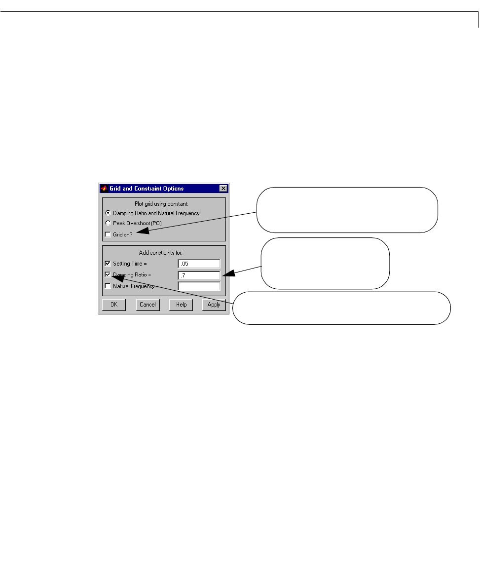
Our designspecificationsrequire that the (2 percent)settlingt ime be less than
.05 seconds,and the maximum overshootless than 5 percent. For second-order
systems, the overshoot requirement can be translated directly as a
requirement on the damping ratio of about .7
(see [2]).
After you enterthese valuesin the appropriatetext fields for our specifications,
your
Grid and Constraint Options window looks like this.
Check this box to place a grid on the root locus,
either for lines of constant damping ratio (with circles
of constant natural frequency), or lines of constant peak
overshoot.
You can enter lists of numbers here to
specify several boundaries for any of
these criteria. Separate numbers in a
list by spaces or commas.
Checks in these boxes indicate the boundaries will appear on the root
locus once you select
OK or Apply. Unchecking them toggles the
boundary off.