
User`s guide
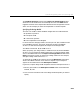
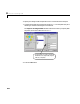
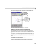
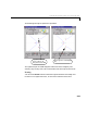
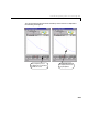
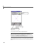
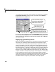
Table Of Contents
- Preface
- Quick Start
- LTI Models
- Introduction
- Creating LTI Models
- LTI Properties
- Model Conversion
- Time Delays
- Simulink Block for LTI Systems
- References
- Operations on LTI Models
- Arrays of LTI Models
- Model Analysis Tools
- The LTI Viewer
- Introduction
- Getting Started Using the LTI Viewer: An Example
- The LTI Viewer Menus
- The Right-Click Menus
- The LTI Viewer Tools Menu
- Simulink LTI Viewer
- Control Design Tools
- The Root Locus Design GUI
- Introduction
- A Servomechanism Example
- Controller Design Using the Root Locus Design GUI
- Additional Root Locus Design GUI Features
- References
- Design Case Studies
- Reliable Computations
- Reference
- Category Tables
- acker
- append
- augstate
- balreal
- bode
- c2d
- canon
- care
- chgunits
- connect
- covar
- ctrb
- ctrbf
- d2c
- d2d
- damp
- dare
- dcgain
- delay2z
- dlqr
- dlyap
- drmodel, drss
- dsort
- dss
- dssdata
- esort
- estim
- evalfr
- feedback
- filt
- frd
- frdata
- freqresp
- gensig
- get
- gram
- hasdelay
- impulse
- initial
- inv
- isct, isdt
- isempty
- isproper
- issiso
- kalman
- kalmd
- lft
- lqgreg
- lqr
- lqrd
- lqry
- lsim
- ltiview
- lyap
- margin
- minreal
- modred
- ndims
- ngrid
- nichols
- norm
- nyquist
- obsv
- obsvf
- ord2
- pade
- parallel
- place
- pole
- pzmap
- reg
- reshape
- rlocfind
- rlocus
- rltool
- rmodel, rss
- series
- set
- sgrid
- sigma
- size
- sminreal
- ss
- ss2ss
- ssbal
- ssdata
- stack
- step
- tf
- tfdata
- totaldelay
- zero
- zgrid
- zpk
- zpkdata
- Index

Controller Design Using the Root Locus Design GUI
8-11
The Feedback Structure portionoftheImport LTI De sign Model window
shows the current selection for the closed-loop structure. The
Other button
toggles the location of the compensator between the two configurations shown
above. For this example you want the compensator in the forward path.
Specifying the Design Model
The S ISO LTI models in either feedback configuration are coded a s follows:
•
F represents a pre-filter.
•
P is the plant model.
•
H is the s ens o r dynamics.
•
K is the compen sator to be design ed.
In terms of the GUI design procedure, once they are set,
F, P ,andHare fixed
in the feedb ack struct ure. T his trip le, a long wit h the choice of feedback
structure, is referred to throughout this chapter as the design model.
The default values for
F, P, H,andKare a ll 1.
When you specify your design model, in addition to
F, P, H, and the feedback
structure, you can specify the design model name. To name the design model,
click in the ed ita ble t ext b ox i n the
Import LTI Desi gn Mo del window below
Name, and enter the name you want for the design model. For this example,
change the d es ig n model name t o
Gservo.
To specify
F, P,andHfor this example, we use the Workspac e ra dio button,
which is the defaul t select ion. A list of the LTI objec ts in your workspace
appears in the model listbox under
Workspace Contents.
In general, to import design model components from the workspace to the GUI:
1 SelectagivenmodelintheWork sp ac e Contents listboxtobeloadedinto
either
F, P,orH.
2 Click on the arrow buttons next to the design model component you want to
spec if y.