
User`s guide

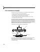

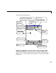

Table Of Contents
- Preface
- Quick Start
- LTI Models
- Introduction
- Creating LTI Models
- LTI Properties
- Model Conversion
- Time Delays
- Simulink Block for LTI Systems
- References
- Operations on LTI Models
- Arrays of LTI Models
- Model Analysis Tools
- The LTI Viewer
- Introduction
- Getting Started Using the LTI Viewer: An Example
- The LTI Viewer Menus
- The Right-Click Menus
- The LTI Viewer Tools Menu
- Simulink LTI Viewer
- Control Design Tools
- The Root Locus Design GUI
- Introduction
- A Servomechanism Example
- Controller Design Using the Root Locus Design GUI
- Additional Root Locus Design GUI Features
- References
- Design Case Studies
- Reliable Computations
- Reference
- Category Tables
- acker
- append
- augstate
- balreal
- bode
- c2d
- canon
- care
- chgunits
- connect
- covar
- ctrb
- ctrbf
- d2c
- d2d
- damp
- dare
- dcgain
- delay2z
- dlqr
- dlyap
- drmodel, drss
- dsort
- dss
- dssdata
- esort
- estim
- evalfr
- feedback
- filt
- frd
- frdata
- freqresp
- gensig
- get
- gram
- hasdelay
- impulse
- initial
- inv
- isct, isdt
- isempty
- isproper
- issiso
- kalman
- kalmd
- lft
- lqgreg
- lqr
- lqrd
- lqry
- lsim
- ltiview
- lyap
- margin
- minreal
- modred
- ndims
- ngrid
- nichols
- norm
- nyquist
- obsv
- obsvf
- ord2
- pade
- parallel
- place
- pole
- pzmap
- reg
- reshape
- rlocfind
- rlocus
- rltool
- rmodel, rss
- series
- set
- sgrid
- sigma
- size
- sminreal
- ss
- ss2ss
- ssbal
- ssdata
- stack
- step
- tf
- tfdata
- totaldelay
- zero
- zgrid
- zpk
- zpkdata
- Index
Controller Design Using the Root Locus Design GUI
8-7
This brings up the following GUI.
Importing Models into the Root Locus Design GUI
The Root Locus Design GUI operates on SISO LTI models constructed using
either
tf, zpk,orss (for detail on creating models, see “Creating LTI Models”
in Chapter 2).
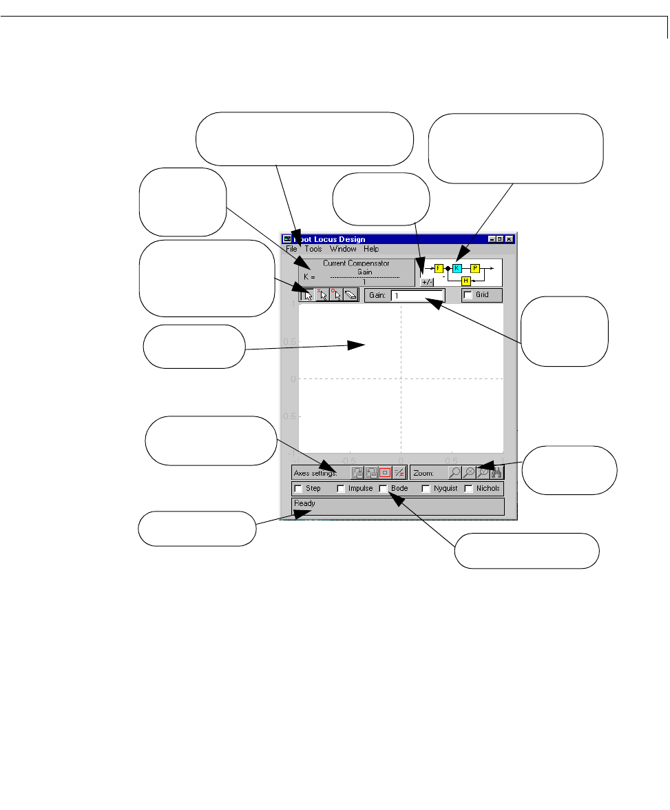
Status bar for providing
Click on these boxes to open
Zoom into or out of
Save/retrieve root locus
axes limits and aspect ratios
the root locus plot.
Click on K to view/change the
compensator, and on P, F, or H to view
the design model characteristics.
The feedback structure:
system response analysis tools.
These are the main menus for importing/
exporting of models, and editing them. You
can also perform discrete/continuous conversion.
Edit the gain set
point to change
the closed-loop
pole locations.
Compensator de-
scription: The de-
fault compensator
is
K
=1.
Root locus toolbar buttons to
drag, add, or erase compensa-
tor poles and zeros, or to drag
the closed-loop poles
Plot region to display
the root locus
Toggle between
positive/negative
feedback.
information