
User`s guide
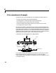
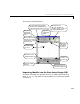
Table Of Contents
- Preface
- Quick Start
- LTI Models
- Introduction
- Creating LTI Models
- LTI Properties
- Model Conversion
- Time Delays
- Simulink Block for LTI Systems
- References
- Operations on LTI Models
- Arrays of LTI Models
- Model Analysis Tools
- The LTI Viewer
- Introduction
- Getting Started Using the LTI Viewer: An Example
- The LTI Viewer Menus
- The Right-Click Menus
- The LTI Viewer Tools Menu
- Simulink LTI Viewer
- Control Design Tools
- The Root Locus Design GUI
- Introduction
- A Servomechanism Example
- Controller Design Using the Root Locus Design GUI
- Additional Root Locus Design GUI Features
- References
- Design Case Studies
- Reliable Computations
- Reference
- Category Tables
- acker
- append
- augstate
- balreal
- bode
- c2d
- canon
- care
- chgunits
- connect
- covar
- ctrb
- ctrbf
- d2c
- d2d
- damp
- dare
- dcgain
- delay2z
- dlqr
- dlyap
- drmodel, drss
- dsort
- dss
- dssdata
- esort
- estim
- evalfr
- feedback
- filt
- frd
- frdata
- freqresp
- gensig
- get
- gram
- hasdelay
- impulse
- initial
- inv
- isct, isdt
- isempty
- isproper
- issiso
- kalman
- kalmd
- lft
- lqgreg
- lqr
- lqrd
- lqry
- lsim
- ltiview
- lyap
- margin
- minreal
- modred
- ndims
- ngrid
- nichols
- norm
- nyquist
- obsv
- obsvf
- ord2
- pade
- parallel
- place
- pole
- pzmap
- reg
- reshape
- rlocfind
- rlocus
- rltool
- rmodel, rss
- series
- set
- sgrid
- sigma
- size
- sminreal
- ss
- ss2ss
- ssbal
- ssdata
- stack
- step
- tf
- tfdata
- totaldelay
- zero
- zgrid
- zpk
- zpkdata
- Index
8 The Root Locus Design GUI
8-4
A Servomechanism Example
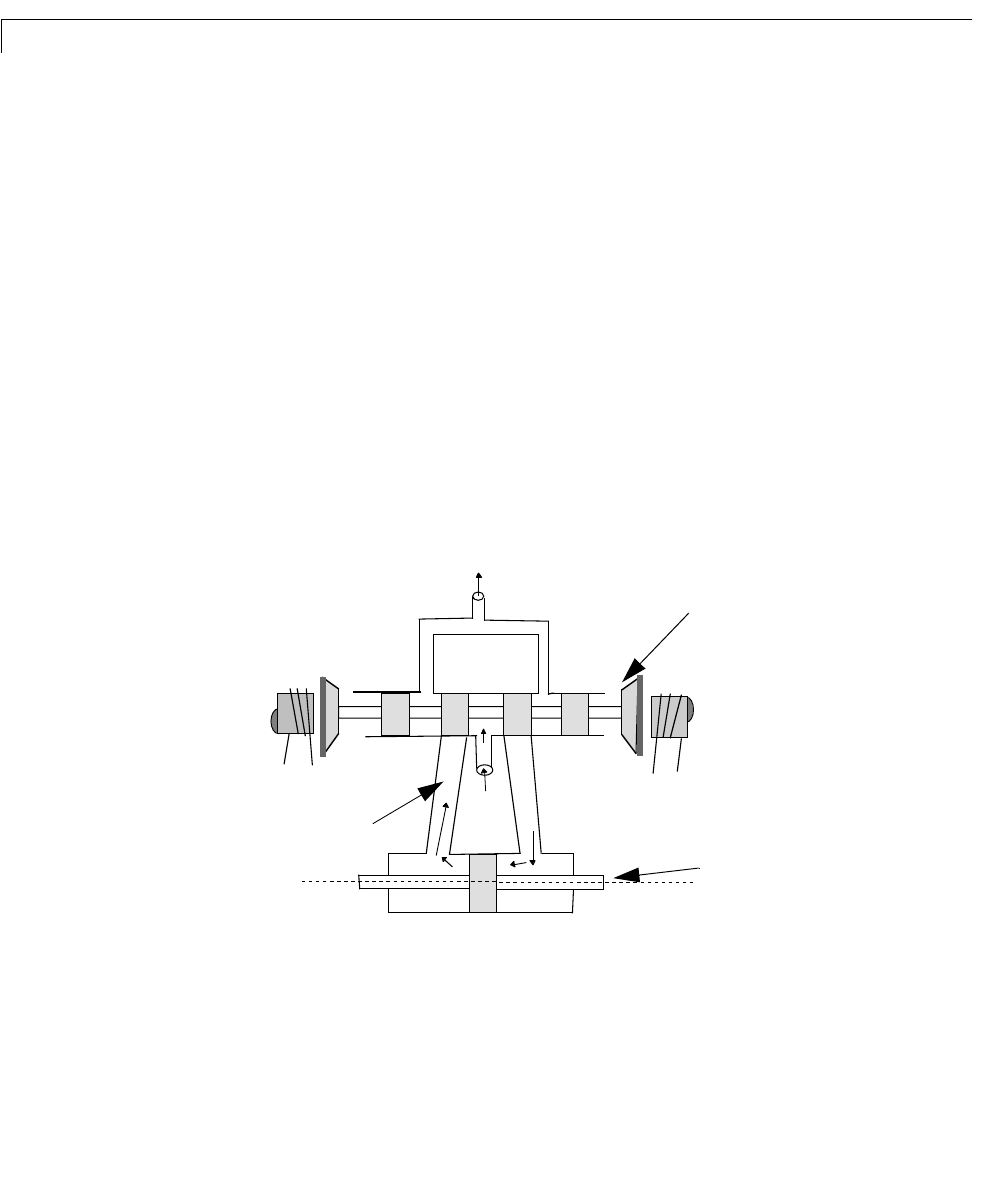
A simple version of an electrohydraulic servomechanism model consists of:
• A push-pull amplifier (a pair of electromagnets)
• A sliding spool in a vessel of high pressure hydraulic fluid
• Valve openings in the vessel to allow for fluid to flow
• A central chamber with a piston-driven ram to deliver force to a load
• A symmetrical fluid return vessel
The force on the spool is proportional to the current in the electromagnet coil.
As the spool moves, the valve opens, allowing the high pressure hydraulic fluid
to flow through the chamber. The moving fluid forces the piston to move in the
opposite direction of the spool. In [1], linearized models for the electromagnetic
amplifier, the valve spool dynamics, and the ram dynamics are derived, and a
detaileddescriptionofthistypeofservomechanismisprovided.
A schematic of this servomechanism is depicted below.
If you want to use this servomechanism for position control, you can use the
input voltage to the electromagnet to control the ram position. When
measurements of the ram position are available, you can use feedback for the
ram position control.
Return
Pressure
Load
Push-pull
amplifier
Push-pull
amplifier
Piston-driven ram
Spool
Hydraulic fluid