
User`s guide
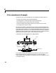
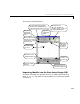
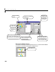
Table Of Contents
- Preface
- Quick Start
- LTI Models
- Introduction
- Creating LTI Models
- LTI Properties
- Model Conversion
- Time Delays
- Simulink Block for LTI Systems
- References
- Operations on LTI Models
- Arrays of LTI Models
- Model Analysis Tools
- The LTI Viewer
- Introduction
- Getting Started Using the LTI Viewer: An Example
- The LTI Viewer Menus
- The Right-Click Menus
- The LTI Viewer Tools Menu
- Simulink LTI Viewer
- Control Design Tools
- The Root Locus Design GUI
- Introduction
- A Servomechanism Example
- Controller Design Using the Root Locus Design GUI
- Additional Root Locus Design GUI Features
- References
- Design Case Studies
- Reliable Computations
- Reference
- Category Tables
- acker
- append
- augstate
- balreal
- bode
- c2d
- canon
- care
- chgunits
- connect
- covar
- ctrb
- ctrbf
- d2c
- d2d
- damp
- dare
- dcgain
- delay2z
- dlqr
- dlyap
- drmodel, drss
- dsort
- dss
- dssdata
- esort
- estim
- evalfr
- feedback
- filt
- frd
- frdata
- freqresp
- gensig
- get
- gram
- hasdelay
- impulse
- initial
- inv
- isct, isdt
- isempty
- isproper
- issiso
- kalman
- kalmd
- lft
- lqgreg
- lqr
- lqrd
- lqry
- lsim
- ltiview
- lyap
- margin
- minreal
- modred
- ndims
- ngrid
- nichols
- norm
- nyquist
- obsv
- obsvf
- ord2
- pade
- parallel
- place
- pole
- pzmap
- reg
- reshape
- rlocfind
- rlocus
- rltool
- rmodel, rss
- series
- set
- sgrid
- sigma
- size
- sminreal
- ss
- ss2ss
- ssbal
- ssdata
- stack
- step
- tf
- tfdata
- totaldelay
- zero
- zgrid
- zpk
- zpkdata
- Index

8 The Root Locus Design GUI
8-2
Introduction
The root locus method is used to descri be the trajectories in the complex plane
of the closed-loop poles of a SISO feedback system as one parameter ( usually a
gain) varies over a continuous range of values.
Along with the MATLAB command line function
rlocus, the Control System
Toolbox provides the Root Locus Design graphical user interface (GUI) for
implementing root locus methods on single-input/single-output (SISO) LTI
models defined using
zpk, tf,orss.
In a d dition to plotting root loci, the Root Locus Design GUI is an interactive
design tool that can be used to:
• Analyze the root locus plot for a SISO LTI control system
• Specify the parameters of a feedback compensator: poles, zeros, and gain
• Examine how changing the compensator parameters effects changes in t he
root locus and various closed-loop system responses (step response, Bode
plot, Nyquist plot, or Nichols chart)
This chapter explains how to use the Root Locus Design GUI, in part, through
an example involving an electrohydraulic servomechanism comprised of an
electrohydraulic amplifier, a valve, and a ram. These types of
servomechanisms can be made quite small, and a re used for position control.
Details on the modelingofelectrohydraulic position control mechanisms canbe
found in [1].
After an explanation of the servomechanism control system, the following
operationsontheRootLocusDesignGUIarecoveredinthesection,“ Controller
Design Using the Root Locus Design GUI” on page 8-6:
• Opening the Root Locus Design GUI
• Importing models into the Root Locus Design GUI
• Changing the gain set point and zooming
• Displaying system responses
• Designing the compensator to meet specifications:
- Specifying the design region boundaries on the root locus
- Placing compensator poles and zeros