
User`s guide
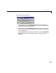
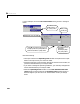
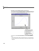
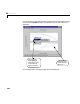
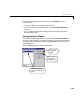


Table Of Contents
- Preface
- Quick Start
- LTI Models
- Introduction
- Creating LTI Models
- LTI Properties
- Model Conversion
- Time Delays
- Simulink Block for LTI Systems
- References
- Operations on LTI Models
- Arrays of LTI Models
- Model Analysis Tools
- The LTI Viewer
- Introduction
- Getting Started Using the LTI Viewer: An Example
- The LTI Viewer Menus
- The Right-Click Menus
- The LTI Viewer Tools Menu
- Simulink LTI Viewer
- Control Design Tools
- The Root Locus Design GUI
- Introduction
- A Servomechanism Example
- Controller Design Using the Root Locus Design GUI
- Additional Root Locus Design GUI Features
- References
- Design Case Studies
- Reliable Computations
- Reference
- Category Tables
- acker
- append
- augstate
- balreal
- bode
- c2d
- canon
- care
- chgunits
- connect
- covar
- ctrb
- ctrbf
- d2c
- d2d
- damp
- dare
- dcgain
- delay2z
- dlqr
- dlyap
- drmodel, drss
- dsort
- dss
- dssdata
- esort
- estim
- evalfr
- feedback
- filt
- frd
- frdata
- freqresp
- gensig
- get
- gram
- hasdelay
- impulse
- initial
- inv
- isct, isdt
- isempty
- isproper
- issiso
- kalman
- kalmd
- lft
- lqgreg
- lqr
- lqrd
- lqry
- lsim
- ltiview
- lyap
- margin
- minreal
- modred
- ndims
- ngrid
- nichols
- norm
- nyquist
- obsv
- obsvf
- ord2
- pade
- parallel
- place
- pole
- pzmap
- reg
- reshape
- rlocfind
- rlocus
- rltool
- rmodel, rss
- series
- set
- sgrid
- sigma
- size
- sminreal
- ss
- ss2ss
- ssbal
- ssdata
- stack
- step
- tf
- tfdata
- totaldelay
- zero
- zgrid
- zpk
- zpkdata
- Index

Simulink LTI Viewer
6-61
• While the Operating Point window is in the Initial state in Simulink
diagram
mode, the linearization values used by the Simulink LTI Viewer
are updated as you change any state values in your Simulink diagram.
• To use the MATLAB command line to change Simulink diagram initial state
values
- Select
Parameters under the Simulation menu on your Simulink
diagram.
- Choose the
Workspace I/O ta b in the Simulation Parameters window.
- Load initial states from the MATLAB worksp ac e using the approp r iate
textbox.
Modifying the Block Parameters
You have the option of modifying any of your Simulink model block
parameters, such asGain block gainvalues or LTI block poles andzeros, before
you import your analysis model into the Simulink LTI Viewer.
Performing Linear Analysis
Once you have specified your analysis model, you are ready to analyze it with
the Simulink LTI Viewer.
Let’s use the Simulink LTI Viewer to compare the Bode plots of two different
linearized analysis models. The procedure for carrying out this analysis on the
van der Pol example involves:
• Importing a linearized analysis mo del to the Simulink LTI Viewer.
• Analyzing the Bode plot of the linearized analysis model.
• Specifying another analysis model.
• Importing the second linearized analysis model to compare the Bode plots of
both linearized analysis models.