
User`s guide
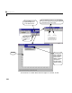
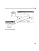
Table Of Contents
- Preface
- Quick Start
- LTI Models
- Introduction
- Creating LTI Models
- LTI Properties
- Model Conversion
- Time Delays
- Simulink Block for LTI Systems
- References
- Operations on LTI Models
- Arrays of LTI Models
- Model Analysis Tools
- The LTI Viewer
- Introduction
- Getting Started Using the LTI Viewer: An Example
- The LTI Viewer Menus
- The Right-Click Menus
- The LTI Viewer Tools Menu
- Simulink LTI Viewer
- Control Design Tools
- The Root Locus Design GUI
- Introduction
- A Servomechanism Example
- Controller Design Using the Root Locus Design GUI
- Additional Root Locus Design GUI Features
- References
- Design Case Studies
- Reliable Computations
- Reference
- Category Tables
- acker
- append
- augstate
- balreal
- bode
- c2d
- canon
- care
- chgunits
- connect
- covar
- ctrb
- ctrbf
- d2c
- d2d
- damp
- dare
- dcgain
- delay2z
- dlqr
- dlyap
- drmodel, drss
- dsort
- dss
- dssdata
- esort
- estim
- evalfr
- feedback
- filt
- frd
- frdata
- freqresp
- gensig
- get
- gram
- hasdelay
- impulse
- initial
- inv
- isct, isdt
- isempty
- isproper
- issiso
- kalman
- kalmd
- lft
- lqgreg
- lqr
- lqrd
- lqry
- lsim
- ltiview
- lyap
- margin
- minreal
- modred
- ndims
- ngrid
- nichols
- norm
- nyquist
- obsv
- obsvf
- ord2
- pade
- parallel
- place
- pole
- pzmap
- reg
- reshape
- rlocfind
- rlocus
- rltool
- rmodel, rss
- series
- set
- sgrid
- sigma
- size
- sminreal
- ss
- ss2ss
- ssbal
- ssdata
- stack
- step
- tf
- tfdata
- totaldelay
- zero
- zgrid
- zpk
- zpkdata
- Index
Simulink LTI Viewer
6-57
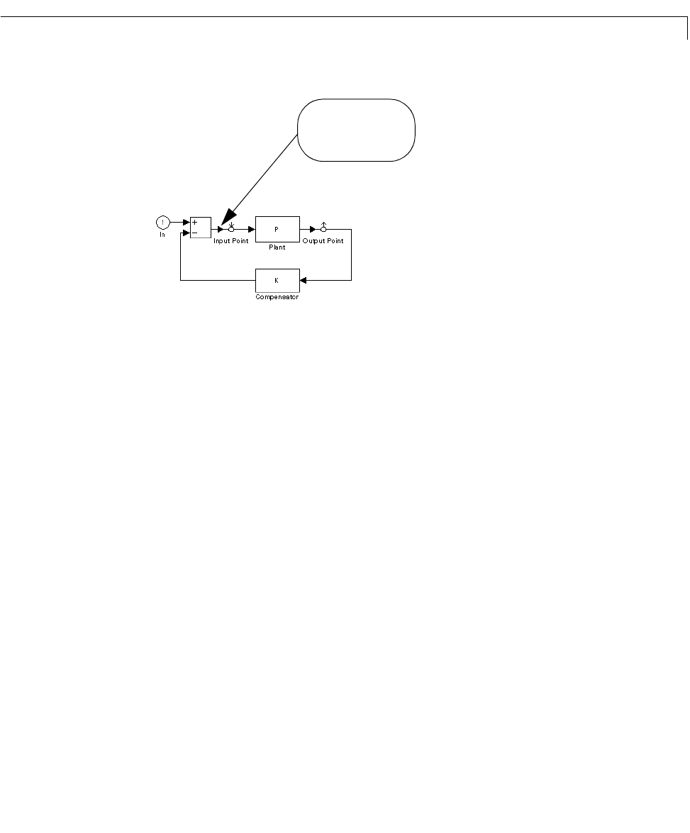
Consider the following simple diagram.
Based on the location of the Input Point and Output Point blocks, you might
think that the analysis model specified by these blocks is simply the plant
model,P. However,due tothe feedback loop, this analysis model is actually the
closed-loop transfer function .
If you want to analyze the (open-loop) plant P instead,youneedtoopenthe
loop, for example, by deleting the line between the Sum and Input Point blocks.
Setting the Operating Conditions
If you have nonlinear components in your Simulink model, the Simulink LTI
Viewer automatica lly linearize s them when you se le ct
Get Line arized Mod el.
The Simulink LTI Viewe r uses the initial stat e values you set in the Simulink
diagram as default settings for line arization po ints for t he s ta te s i n the
diagram. The default input value s fo r this linearizati on are zero. Yo u also have
the option to linearize about the operating conditions of your choice.
If youwant youranalysis modelto be linearizedabout zero state, orother state
and input operati ng conditions , follow these steps before selecting
Get
Linearized Model
:
Delete this line to isolate
the plant, P
, for open
loop analysis.
P 1 PK
+()⁄