
User`s guide
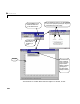
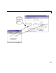
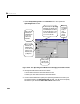
Table Of Contents
- Preface
- Quick Start
- LTI Models
- Introduction
- Creating LTI Models
- LTI Properties
- Model Conversion
- Time Delays
- Simulink Block for LTI Systems
- References
- Operations on LTI Models
- Arrays of LTI Models
- Model Analysis Tools
- The LTI Viewer
- Introduction
- Getting Started Using the LTI Viewer: An Example
- The LTI Viewer Menus
- The Right-Click Menus
- The LTI Viewer Tools Menu
- Simulink LTI Viewer
- Control Design Tools
- The Root Locus Design GUI
- Introduction
- A Servomechanism Example
- Controller Design Using the Root Locus Design GUI
- Additional Root Locus Design GUI Features
- References
- Design Case Studies
- Reliable Computations
- Reference
- Category Tables
- acker
- append
- augstate
- balreal
- bode
- c2d
- canon
- care
- chgunits
- connect
- covar
- ctrb
- ctrbf
- d2c
- d2d
- damp
- dare
- dcgain
- delay2z
- dlqr
- dlyap
- drmodel, drss
- dsort
- dss
- dssdata
- esort
- estim
- evalfr
- feedback
- filt
- frd
- frdata
- freqresp
- gensig
- get
- gram
- hasdelay
- impulse
- initial
- inv
- isct, isdt
- isempty
- isproper
- issiso
- kalman
- kalmd
- lft
- lqgreg
- lqr
- lqrd
- lqry
- lsim
- ltiview
- lyap
- margin
- minreal
- modred
- ndims
- ngrid
- nichols
- norm
- nyquist
- obsv
- obsvf
- ord2
- pade
- parallel
- place
- pole
- pzmap
- reg
- reshape
- rlocfind
- rlocus
- rltool
- rmodel, rss
- series
- set
- sgrid
- sigma
- size
- sminreal
- ss
- ss2ss
- ssbal
- ssdata
- stack
- step
- tf
- tfdata
- totaldelay
- zero
- zgrid
- zpk
- zpkdata
- Index

6 The LTI Viewer
6-56
Keep the following in mind when using the Input Point a nd Output Point
blocks to specify analysis models:
• You must p lace at least one Input Point block and one Output Point block
somewhereinthediagraminordertospecifyananalysismodel.
•You can place the Input Point and Output Point blocks on any scalar or
vector signal line in the Simulink model, with the exception of signal lines
connected to any block in the Power System Blockset.
• You can insert Input Point and Output Point blocks at different levels of a
Simulink model hierarchy.
• There is no limit on the number of these blocks you can use.
Removing Input Points and Output Points
There are tw o ways you can remove Input Point or Output Point blocks from
the Simulink model:
1 One by one: Select the Input Point o r Output Point block you wa nt to
remove and delete it as yo u would a ny other S imulink block.
2 All at once: To remove a ll Input Point and Output Point blocks, select
Remove Input/Ou tput Po ints from the Simulink menu in t he LTI Viewer.
When you delete an Input Point or an Output Point block, the signal lines
coming into and out of th is blo ck a re a uto mati cally reconnected.
Specifying Open- Versus Closed-Loop Analysis Models
Placing the Input Point and Output Point blocks on your Simulink model does
not break any connection or isolate any component. As a result, the Simulink
LTI Viewer performs closed-loop analysis whenever your diagram contains
feedback loops. This may sometimes lead to counter-intuitive results, as is
illustrated by the next example.