
User`s guide
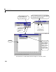
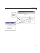
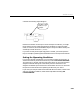
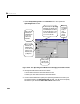
Table Of Contents
- Preface
- Quick Start
- LTI Models
- Introduction
- Creating LTI Models
- LTI Properties
- Model Conversion
- Time Delays
- Simulink Block for LTI Systems
- References
- Operations on LTI Models
- Arrays of LTI Models
- Model Analysis Tools
- The LTI Viewer
- Introduction
- Getting Started Using the LTI Viewer: An Example
- The LTI Viewer Menus
- The Right-Click Menus
- The LTI Viewer Tools Menu
- Simulink LTI Viewer
- Control Design Tools
- The Root Locus Design GUI
- Introduction
- A Servomechanism Example
- Controller Design Using the Root Locus Design GUI
- Additional Root Locus Design GUI Features
- References
- Design Case Studies
- Reliable Computations
- Reference
- Category Tables
- acker
- append
- augstate
- balreal
- bode
- c2d
- canon
- care
- chgunits
- connect
- covar
- ctrb
- ctrbf
- d2c
- d2d
- damp
- dare
- dcgain
- delay2z
- dlqr
- dlyap
- drmodel, drss
- dsort
- dss
- dssdata
- esort
- estim
- evalfr
- feedback
- filt
- frd
- frdata
- freqresp
- gensig
- get
- gram
- hasdelay
- impulse
- initial
- inv
- isct, isdt
- isempty
- isproper
- issiso
- kalman
- kalmd
- lft
- lqgreg
- lqr
- lqrd
- lqry
- lsim
- ltiview
- lyap
- margin
- minreal
- modred
- ndims
- ngrid
- nichols
- norm
- nyquist
- obsv
- obsvf
- ord2
- pade
- parallel
- place
- pole
- pzmap
- reg
- reshape
- rlocfind
- rlocus
- rltool
- rmodel, rss
- series
- set
- sgrid
- sigma
- size
- sminreal
- ss
- ss2ss
- ssbal
- ssdata
- stack
- step
- tf
- tfdata
- totaldelay
- zero
- zgrid
- zpk
- zpkdata
- Index

Simulink LTI Viewer
6-53
• The title bar shows the name of the Simulink model to which it is linked.
• The menu bar contains an additional menu called
Simulink that contains
the following items:
-
Get Linea r ized Model linearizes the Simulink model and imports the
resulting linearized analysis model to the LTI Viewer. Each time you
select this menu item, a ne w version of the linearized analysi s model is
added to the Simulink LTI Viewer workspace.
-
Set Operating Point allows you to set or reset the operating conditions.
-
Remove Input/Output Points clears all Input Point and Output Point
blocks from the diagram.
Specifying the Simulink Model Portion for Analysis
To specify the portion of the Simulink model you want to analyze, mark its
input a nd output signals on t he Simulink model using the Input Point and
Output Point blocks in the
Model_Inputs_and_Outputs window. This defines
an input/outp ut relationship that is linearized a nd anal yze d by t he LTI Viewer.
Adding Input Point or Output Point Blocks to the Diagram
To designate the input and output signals of your analysis model, insert Input
Point and Output Point blocks on the corresponding signal lines in your
Simulink diagram.
For example, to insert an Input Point block on the Simulink model:
1 Grab the Input Point block in the Model_Inputs_and_Outputs window by
clicking on the block and holding the mouse button down.
2 Drag the block to your Simulink model and place it over the line associated
with the desired signal.
3 Release the mouse button. The block should automatically connect to the
line.
4 Ifthe block fails to connect (this may occur, for example, when the line is too
short), resize the line and double-click on the block to force the connection.