
User`s guide
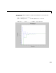
Table Of Contents
- Preface
- Quick Start
- LTI Models
- Introduction
- Creating LTI Models
- LTI Properties
- Model Conversion
- Time Delays
- Simulink Block for LTI Systems
- References
- Operations on LTI Models
- Arrays of LTI Models
- Model Analysis Tools
- The LTI Viewer
- Introduction
- Getting Started Using the LTI Viewer: An Example
- The LTI Viewer Menus
- The Right-Click Menus
- The LTI Viewer Tools Menu
- Simulink LTI Viewer
- Control Design Tools
- The Root Locus Design GUI
- Introduction
- A Servomechanism Example
- Controller Design Using the Root Locus Design GUI
- Additional Root Locus Design GUI Features
- References
- Design Case Studies
- Reliable Computations
- Reference
- Category Tables
- acker
- append
- augstate
- balreal
- bode
- c2d
- canon
- care
- chgunits
- connect
- covar
- ctrb
- ctrbf
- d2c
- d2d
- damp
- dare
- dcgain
- delay2z
- dlqr
- dlyap
- drmodel, drss
- dsort
- dss
- dssdata
- esort
- estim
- evalfr
- feedback
- filt
- frd
- frdata
- freqresp
- gensig
- get
- gram
- hasdelay
- impulse
- initial
- inv
- isct, isdt
- isempty
- isproper
- issiso
- kalman
- kalmd
- lft
- lqgreg
- lqr
- lqrd
- lqry
- lsim
- ltiview
- lyap
- margin
- minreal
- modred
- ndims
- ngrid
- nichols
- norm
- nyquist
- obsv
- obsvf
- ord2
- pade
- parallel
- place
- pole
- pzmap
- reg
- reshape
- rlocfind
- rlocus
- rltool
- rmodel, rss
- series
- set
- sgrid
- sigma
- size
- sminreal
- ss
- ss2ss
- ssbal
- ssdata
- stack
- step
- tf
- tfdata
- totaldelay
- zero
- zgrid
- zpk
- zpkdata
- Index

Time and Frequency Response
5-13
For example,
bode(sys,{0.1 , 100})
draws the Bode plot between 0.1 and 100 radians/second. You can also specify
a particular vector of frequency points as in
w = logspace(–1,2,100)
bode(sys,w)
The logspace command generates a vector w of logarithmically spaced
frequencies starting at rad/s and ending at rad/s. See
the reference page for
linspace for linearly spaced frequency vectors.
Note: In discrete time, the frequency response is evaluated on the unit circle
and the notion of “frequency” should be understood as follows. The upper half
of the unit circle is parametrized by
where is the system sample time and is ca lled the Nyquist frequency.
The variable plays the role of continuous-time freq u ency. We use t h is
“equivalent frequency” as an -axis variable in all discrete-t ime frequency
response plots. In addition, the frequency response is plotted only up to the
Nyquist frequency because it is peri odic with period ( a phenome non
known as aliasing).
Note: An easy way to implement these response-plotting functions is
through the LTI Viewer. See Chapter 6, “The LTI Viewer” for more
information.
Plotting and Comparing Multiple Systems
The LTIViewerprovides one method of plotting various responsesfor multiple
models. SeeChapter6,“TheLTI Viewer”toseehow toaccomplishthis.You can
also use the command line response-plotting functions to plot the response of
10
1
–
0.1= 10
2
100=
ze
jωT
s
= ,0ωω
N
π
T
s
------=≤≤
T
s
ω
N
ω
x
ω
N
2
ω
N