
User`s guide
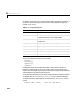
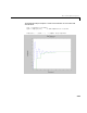
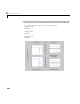
Table Of Contents
- Preface
- Quick Start
- LTI Models
- Introduction
- Creating LTI Models
- LTI Properties
- Model Conversion
- Time Delays
- Simulink Block for LTI Systems
- References
- Operations on LTI Models
- Arrays of LTI Models
- Model Analysis Tools
- The LTI Viewer
- Introduction
- Getting Started Using the LTI Viewer: An Example
- The LTI Viewer Menus
- The Right-Click Menus
- The LTI Viewer Tools Menu
- Simulink LTI Viewer
- Control Design Tools
- The Root Locus Design GUI
- Introduction
- A Servomechanism Example
- Controller Design Using the Root Locus Design GUI
- Additional Root Locus Design GUI Features
- References
- Design Case Studies
- Reliable Computations
- Reference
- Category Tables
- acker
- append
- augstate
- balreal
- bode
- c2d
- canon
- care
- chgunits
- connect
- covar
- ctrb
- ctrbf
- d2c
- d2d
- damp
- dare
- dcgain
- delay2z
- dlqr
- dlyap
- drmodel, drss
- dsort
- dss
- dssdata
- esort
- estim
- evalfr
- feedback
- filt
- frd
- frdata
- freqresp
- gensig
- get
- gram
- hasdelay
- impulse
- initial
- inv
- isct, isdt
- isempty
- isproper
- issiso
- kalman
- kalmd
- lft
- lqgreg
- lqr
- lqrd
- lqry
- lsim
- ltiview
- lyap
- margin
- minreal
- modred
- ndims
- ngrid
- nichols
- norm
- nyquist
- obsv
- obsvf
- ord2
- pade
- parallel
- place
- pole
- pzmap
- reg
- reshape
- rlocfind
- rlocus
- rltool
- rmodel, rss
- series
- set
- sgrid
- sigma
- size
- sminreal
- ss
- ss2ss
- ssbal
- ssdata
- stack
- step
- tf
- tfdata
- totaldelay
- zero
- zgrid
- zpk
- zpkdata
- Index

Time and Frequency Response
5-9
Time and Frequency Response
The Control System Toolbox contains a set of commands that provide the basic
time and frequency domain analysis tools required for control system
engineering. These commandsapply to any kind of LTI model (TF, ZPK, or SS,
continuous or discrete, SISO or MIMO). You can only a pply the frequency
domain analysis tools FRDs. The LTI Viewer provides an integrated graphical
user interface (GUI) to analyze and compare LTI mo dels (see Chapt er 6, “T he
LTI Viewer” for det ails).
Time Responses
Time responses investigate the time-domain transient behavior of LTI models
for particular classes of inputs and disturbances. You can determine such
system characteristics as rise time, settling time, overshoot, and steady-state
error from the time response. The Control System Toolbox provides functions
for step response, impulse response, initial condition response, and general
linear simulations. You can apply these functions to single TF, SS, or ZPK
models or arrays of these types of models. Note that you can simulate the
response to white noise inputs using
lsim and the function rand (see Using
MATLAB to generate random input vectors.
The functions
step, impulse,andinitial automatically generate an
appropriate simulation horizon for the time response plots. Their syntax is
step(sys)
impulse(sys)
initial(sys,x0) % x0 = initial state vector
Time Response
impulse
Impulse response.
initial
Initial condition response.
gensig
Input signal gene rator.
lsim
Simulation of response to arbitrary inputs.
step
Step response.