
Specifications

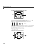
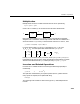
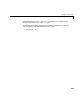
Table Of Contents
- Introduction
- LTI Models
- Operations on LTI Models
- Model Analysis Tools
- Arrays of LTI Models
- Customization
- Setting Toolbox Preferences
- Setting Tool Preferences
- Customizing Response Plot Properties
- Design Case Studies
- Reliable Computations
- GUI Reference
- SISO Design Tool Reference
- Menu Bar
- File
- Import
- Export
- Toolbox Preferences
- Print to Figure
- Close
- Edit
- Undo and Redo
- Root Locus and Bode Diagrams
- SISO Tool Preferences
- View
- Root Locus and Bode Diagrams
- System Data
- Closed Loop Poles
- Design History
- Tools
- Loop Responses
- Continuous/Discrete Conversions
- Draw a Simulink Diagram
- Compensator
- Format
- Edit
- Store
- Retrieve
- Clear
- Window
- Help
- Tool Bar
- Current Compensator
- Feedback Structure
- Root Locus Right-Click Menus
- Bode Diagram Right-Click Menus
- Status Panel
- Menu Bar
- LTI Viewer Reference
- Right-Click Menus for Response Plots
- Function Reference
- Functions by Category
- acker
- allmargin
- append
- augstate
- balreal
- bode
- bodemag
- c2d
- canon
- care
- chgunits
- connect
- covar
- ctrb
- ctrbf
- d2c
- d2d
- damp
- dare
- dcgain
- delay2z
- dlqr
- dlyap
- drss
- dsort
- dss
- dssdata
- esort
- estim
- evalfr
- feedback
- filt
- frd
- frdata
- freqresp
- gensig
- get
- gram
- hasdelay
- impulse
- initial
- interp
- inv
- isct, isdt
- isempty
- isproper
- issiso
- kalman
- kalmd
- lft
- lqgreg
- lqr
- lqrd
- lqry
- lsim
- ltimodels
- ltiprops
- ltiview
- lyap
- margin
- minreal
- modred
- ndims
- ngrid
- nichols
- norm
- nyquist
- obsv
- obsvf
- ord2
- pade
- parallel
- place
- pole
- pzmap
- reg
- reshape
- rlocus
- rss
- series
- set
- sgrid
- sigma
- sisotool
- size
- sminreal
- ss
- ss2ss
- ssbal
- ssdata
- stack
- step
- tf
- tfdata
- totaldelay
- zero
- zgrid
- zpk
- zpkdata
- Index

Extracting and Modifying Subsystems
3-7
Next reassign to and modify the second input channel of T
by typing
T(1,1) = tf(1,[1 0.5]);
T(:,2) = [ 1 ; tf(0.4,[1 0]) ]
Transfer function from input 1 to output...
1
#1: -------
s + 0.5
s – 1
#2: -------------
s^2 + 2 s + 2
Transfer function from input 2 to output...
#1: 1
0.4
#2: ---
s
Referencing FRD Models Through Frequencies
You can extract subsystems from FRD models, as you do with other LTI model
types, by indexing into input andoutput (I/O) dimensions. Youcan also extract
subsystems by indexing into the frequencies of an FRD model.
To index into the frequencies of an FRD model, use the string
'Frequency' (or
any abbreviation, such as,
'freq', as long as it does not conflict with existing
I/O channel or group names)as a keyword.There are two ways you can specify
FRD models using frequencies:
•Using integers to index into the frequency vector of the FRD model
•Using a Boolean (logical) expression to specify desired frequency points in an
FRD model
For example, if
sys is an FRD model with five frequencies, (e.g.,
sys.Frequency=[1 1.1 1.2 1.3 1.4]), then you can create a new FRD model
sys2 by indexing into the frequencies of sys as follows.
sys2 = sys('frequency', 2:3);
T
11
s
()
1 s 0.5+
()⁄