
Specifications
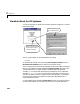

Table Of Contents
- Introduction
- LTI Models
- Operations on LTI Models
- Model Analysis Tools
- Arrays of LTI Models
- Customization
- Setting Toolbox Preferences
- Setting Tool Preferences
- Customizing Response Plot Properties
- Design Case Studies
- Reliable Computations
- GUI Reference
- SISO Design Tool Reference
- Menu Bar
- File
- Import
- Export
- Toolbox Preferences
- Print to Figure
- Close
- Edit
- Undo and Redo
- Root Locus and Bode Diagrams
- SISO Tool Preferences
- View
- Root Locus and Bode Diagrams
- System Data
- Closed Loop Poles
- Design History
- Tools
- Loop Responses
- Continuous/Discrete Conversions
- Draw a Simulink Diagram
- Compensator
- Format
- Edit
- Store
- Retrieve
- Clear
- Window
- Help
- Tool Bar
- Current Compensator
- Feedback Structure
- Root Locus Right-Click Menus
- Bode Diagram Right-Click Menus
- Status Panel
- Menu Bar
- LTI Viewer Reference
- Right-Click Menus for Response Plots
- Function Reference
- Functions by Category
- acker
- allmargin
- append
- augstate
- balreal
- bode
- bodemag
- c2d
- canon
- care
- chgunits
- connect
- covar
- ctrb
- ctrbf
- d2c
- d2d
- damp
- dare
- dcgain
- delay2z
- dlqr
- dlyap
- drss
- dsort
- dss
- dssdata
- esort
- estim
- evalfr
- feedback
- filt
- frd
- frdata
- freqresp
- gensig
- get
- gram
- hasdelay
- impulse
- initial
- interp
- inv
- isct, isdt
- isempty
- isproper
- issiso
- kalman
- kalmd
- lft
- lqgreg
- lqr
- lqrd
- lqry
- lsim
- ltimodels
- ltiprops
- ltiview
- lyap
- margin
- minreal
- modred
- ndims
- ngrid
- nichols
- norm
- nyquist
- obsv
- obsvf
- ord2
- pade
- parallel
- place
- pole
- pzmap
- reg
- reshape
- rlocus
- rss
- series
- set
- sgrid
- sigma
- sisotool
- size
- sminreal
- ss
- ss2ss
- ssbal
- ssdata
- stack
- step
- tf
- tfdata
- totaldelay
- zero
- zgrid
- zpk
- zpkdata
- Index

Extracting and Modifying Subsystems
3-5
Extracting and Modifying Subsystems
Subsystems relate subsets of the inputs and outputs of a system. The transfer
matrix of a subsystem is a submatrix of the system transfer matrix. For
example, if
sys is a system with two inputs, three outputs, and I/O relation
then gives the relation between the first input and third output.
Accordingly, use matrix-like subindexing to extract this subsystem.
SubSys = sys(3,1)
The resulting subsystem SubSys is an LTI model of the same type as sys,with
its sample time, time delay, I/O name, and I/O group property values inherited
from
sys.
For example,if
sys has an input group named controls consisting of channels
one, two, and three, then
SubSys also has an input group named controls with
the first channel of
SubSys assigned to it.
If
sys is a state-space model with matrices a, b, c, d,thesubsystemsys(3,1)
isastate-spacemodelwithdataa, b(:,1), c(3,:), d(3,1).Notethefollowing
rules when extracting subystems:
•In the expression
sys(3,1), the first index selects the output channel while
the second index selects the input channel.
•When extracting a subsystem from a given state-space model, the resulting
state-space model may not be minimal. Use the command
sminreal to
eliminate unnecessary states in the subsystem.
You can use similar syntax to modify the LTI model
sys. For example,
sys(3,1) = NewSubSys
redefines the I/O relation between the first input and third output, provided
NewSubSys is a SISO LTI model.
yHu=
H 31
,()
y
3
H 3,1
()
u
1
=