
Specifications
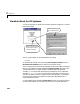

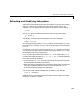
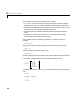
Table Of Contents
- Introduction
- LTI Models
- Operations on LTI Models
- Model Analysis Tools
- Arrays of LTI Models
- Customization
- Setting Toolbox Preferences
- Setting Tool Preferences
- Customizing Response Plot Properties
- Design Case Studies
- Reliable Computations
- GUI Reference
- SISO Design Tool Reference
- Menu Bar
- File
- Import
- Export
- Toolbox Preferences
- Print to Figure
- Close
- Edit
- Undo and Redo
- Root Locus and Bode Diagrams
- SISO Tool Preferences
- View
- Root Locus and Bode Diagrams
- System Data
- Closed Loop Poles
- Design History
- Tools
- Loop Responses
- Continuous/Discrete Conversions
- Draw a Simulink Diagram
- Compensator
- Format
- Edit
- Store
- Retrieve
- Clear
- Window
- Help
- Tool Bar
- Current Compensator
- Feedback Structure
- Root Locus Right-Click Menus
- Bode Diagram Right-Click Menus
- Status Panel
- Menu Bar
- LTI Viewer Reference
- Right-Click Menus for Response Plots
- Function Reference
- Functions by Category
- acker
- allmargin
- append
- augstate
- balreal
- bode
- bodemag
- c2d
- canon
- care
- chgunits
- connect
- covar
- ctrb
- ctrbf
- d2c
- d2d
- damp
- dare
- dcgain
- delay2z
- dlqr
- dlyap
- drss
- dsort
- dss
- dssdata
- esort
- estim
- evalfr
- feedback
- filt
- frd
- frdata
- freqresp
- gensig
- get
- gram
- hasdelay
- impulse
- initial
- interp
- inv
- isct, isdt
- isempty
- isproper
- issiso
- kalman
- kalmd
- lft
- lqgreg
- lqr
- lqrd
- lqry
- lsim
- ltimodels
- ltiprops
- ltiview
- lyap
- margin
- minreal
- modred
- ndims
- ngrid
- nichols
- norm
- nyquist
- obsv
- obsvf
- ord2
- pade
- parallel
- place
- pole
- pzmap
- reg
- reshape
- rlocus
- rss
- series
- set
- sgrid
- sigma
- sisotool
- size
- sminreal
- ss
- ss2ss
- ssbal
- ssdata
- stack
- step
- tf
- tfdata
- totaldelay
- zero
- zgrid
- zpk
- zpkdata
- Index
2 LTI Models
2-54
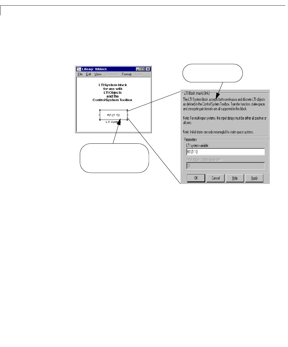
Simulink Block for LTI Systems
You can incorporate LTI objects into Simulink diagrams using the LTI System
block shown below.
The LTI System block can be accessed either by typing
ltiblock
at the MATLAB prompt or by selecting Control System Toolbox from the
Blocksets and Toolboxes section of the main Simulink library.
TheLTISystem block consists of the dialog box shown on the right inthefigure
above. In the editable text box labeled
LTI system variable, enter either the
variable name of an LTI object located in the MATLAB workspace (for
example,
sys) or a MATLAB expression that evaluates to an LTI object (for
example,
tf(1,[1 1])). The LTI System block accepts both continuous and
discrete LTI objects in either transfer function, zero-pole-gain, or state-space
form. Simulink converts the model to its state-space equivalent prior to
initializing the simulation.
Use the editable text box labeled
Initial states to enter an initial state vector
for state-space models. The concept of “initial state” is not well-defined for
Double-click on the block in your
Simulink diagram to display or
modify model information.
This mask is linked to an LTI
block in a Simulink diagram.