
Specifications
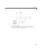


Table Of Contents
- Introduction
- LTI Models
- Operations on LTI Models
- Model Analysis Tools
- Arrays of LTI Models
- Customization
- Setting Toolbox Preferences
- Setting Tool Preferences
- Customizing Response Plot Properties
- Design Case Studies
- Reliable Computations
- GUI Reference
- SISO Design Tool Reference
- Menu Bar
- File
- Import
- Export
- Toolbox Preferences
- Print to Figure
- Close
- Edit
- Undo and Redo
- Root Locus and Bode Diagrams
- SISO Tool Preferences
- View
- Root Locus and Bode Diagrams
- System Data
- Closed Loop Poles
- Design History
- Tools
- Loop Responses
- Continuous/Discrete Conversions
- Draw a Simulink Diagram
- Compensator
- Format
- Edit
- Store
- Retrieve
- Clear
- Window
- Help
- Tool Bar
- Current Compensator
- Feedback Structure
- Root Locus Right-Click Menus
- Bode Diagram Right-Click Menus
- Status Panel
- Menu Bar
- LTI Viewer Reference
- Right-Click Menus for Response Plots
- Function Reference
- Functions by Category
- acker
- allmargin
- append
- augstate
- balreal
- bode
- bodemag
- c2d
- canon
- care
- chgunits
- connect
- covar
- ctrb
- ctrbf
- d2c
- d2d
- damp
- dare
- dcgain
- delay2z
- dlqr
- dlyap
- drss
- dsort
- dss
- dssdata
- esort
- estim
- evalfr
- feedback
- filt
- frd
- frdata
- freqresp
- gensig
- get
- gram
- hasdelay
- impulse
- initial
- interp
- inv
- isct, isdt
- isempty
- isproper
- issiso
- kalman
- kalmd
- lft
- lqgreg
- lqr
- lqrd
- lqry
- lsim
- ltimodels
- ltiprops
- ltiview
- lyap
- margin
- minreal
- modred
- ndims
- ngrid
- nichols
- norm
- nyquist
- obsv
- obsvf
- ord2
- pade
- parallel
- place
- pole
- pzmap
- reg
- reshape
- rlocus
- rss
- series
- set
- sgrid
- sigma
- sisotool
- size
- sminreal
- ss
- ss2ss
- ssbal
- ssdata
- stack
- step
- tf
- tfdata
- totaldelay
- zero
- zgrid
- zpk
- zpkdata
- Index

LTI Properties
2-35
Input Names and Output Names
You can use the InputName and OutputName properties (in short, I/O names) to
assign names to any or all of the input and output channels in your LTI model.
For example, you can create a SISO model with input
thrust, output
velocity, and transfer function by typing
h = tf(1,[1 10]);
set(h,'inputname','thrust','outputname','velocity',...
'variable','p')
Equivalently, you can set these properties directly by typing
h = tf(1,[1 10],'inputname','thrust',...
'outputname','velocity',...
'variable','p')
This produces
Transfer function from input "thrust" to output "velocity":
1
------
p + 10
Note how the display reflects the input and output names and the variable
selection.
In the MIMO case, usecell vectors of strings tospecify input or output channel
names. For example, type
num = {3 , [1 2]};
den = {[1 10] , [1 0]};
H = tf(num,den); % H(s) has one output and two inputs
set(H,'inputname',{'temperature' ; 'pressure'})
The specified input names appear in the display of H.
Transfer function from input "temperature" to output:
3
------
s + 10
Transfer function from input "pressure" to output:
Hp
()
1 p 10+
()⁄
=