
Specifications
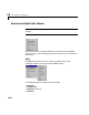
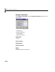
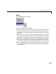
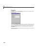

Table Of Contents
- Introduction
- LTI Models
- Operations on LTI Models
- Model Analysis Tools
- Arrays of LTI Models
- Customization
- Setting Toolbox Preferences
- Setting Tool Preferences
- Customizing Response Plot Properties
- Design Case Studies
- Reliable Computations
- GUI Reference
- SISO Design Tool Reference
- Menu Bar
- File
- Import
- Export
- Toolbox Preferences
- Print to Figure
- Close
- Edit
- Undo and Redo
- Root Locus and Bode Diagrams
- SISO Tool Preferences
- View
- Root Locus and Bode Diagrams
- System Data
- Closed Loop Poles
- Design History
- Tools
- Loop Responses
- Continuous/Discrete Conversions
- Draw a Simulink Diagram
- Compensator
- Format
- Edit
- Store
- Retrieve
- Clear
- Window
- Help
- Tool Bar
- Current Compensator
- Feedback Structure
- Root Locus Right-Click Menus
- Bode Diagram Right-Click Menus
- Status Panel
- Menu Bar
- LTI Viewer Reference
- Right-Click Menus for Response Plots
- Function Reference
- Functions by Category
- acker
- allmargin
- append
- augstate
- balreal
- bode
- bodemag
- c2d
- canon
- care
- chgunits
- connect
- covar
- ctrb
- ctrbf
- d2c
- d2d
- damp
- dare
- dcgain
- delay2z
- dlqr
- dlyap
- drss
- dsort
- dss
- dssdata
- esort
- estim
- evalfr
- feedback
- filt
- frd
- frdata
- freqresp
- gensig
- get
- gram
- hasdelay
- impulse
- initial
- interp
- inv
- isct, isdt
- isempty
- isproper
- issiso
- kalman
- kalmd
- lft
- lqgreg
- lqr
- lqrd
- lqry
- lsim
- ltimodels
- ltiprops
- ltiview
- lyap
- margin
- minreal
- modred
- ndims
- ngrid
- nichols
- norm
- nyquist
- obsv
- obsvf
- ord2
- pade
- parallel
- place
- pole
- pzmap
- reg
- reshape
- rlocus
- rss
- series
- set
- sgrid
- sigma
- sisotool
- size
- sminreal
- ss
- ss2ss
- ssbal
- ssdata
- stack
- step
- tf
- tfdata
- totaldelay
- zero
- zgrid
- zpk
- zpkdata
- Index

13 SISO Design Tool Reference
13-32
•Lead
•Lag
•Notch
In all but the integrator and differentiator, once you select the configuration,
your cursor changes toan ‘x’. Toaddtheitemtoyourcompensatordesign, place
the x at the desired location on the plot and left-click your mouse. You will see
the root locus design automatically update to include the new compensator
dynamics.
The notch filter has three adjustable parameters. For a discussion about how
to add and adjust notch filters, see Adding a Notch Filter in Getting Started
with the Control System Toolbox.
Delete Pole/Zero
Select Delete Pole/Zero to delete poles and zeros from your compensator
design. When you make this selection, your cursor changes to an eraser. Place
the eraser over the pole or zero you want to delete and left-click your mouse.
Note the following:
•You can only delete compensator poles and zeros. Plant (
G in the feedback
structure panel) poles and zeros cannot be altered.
•If you delete one of a pair of poles or zeros, the other member of the pair is
also removed.
Edit Compensator
Edit Compensator opens the Edit Compensator window, which you can use
to change the compensator gain and add or remove compensator poles and
zeros from your design. See “Edit” for a discussion of this window.