
Technical information

INFORMATION
EN / WHISPER 3.5 / December 2009 / Copyright © 2009 Mastervolt 11
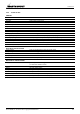
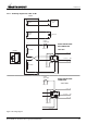
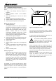
2.4.2 Local control panel
1 Fuse 10A 6 Contact / fuel pump LED
2 Fuse 30A 7 Autostart LED
3 Start LED 8 Failure LED
4 Glow LED 9 Start/stop button
5 Pull to stop LED
Figure 3: Local control panel.
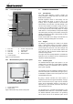
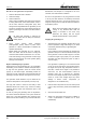
2.4.3 MasterView Easy remote control panel
1 Touch screen Display
2 Display on/off
Figure 4: MasterView Easy remote control panel.
2.5 TECHNICAL INFORMATION
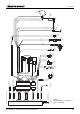
2.5.1 AC alternator
The single phase alternator is directly coupled, one
bearing, brushless, rotating field design, two poles (3000
RPM) and self regulating.
Residual magnetism causes a small voltage over the
stator windings and allows a current to flow in the
windings, which is magnified because of the feed back
effect between rotor and stator. The field windings in the
rotor are short-circuited over a diode to rectify the current.
A capacitor over an additional winding in the stator which
is at an angle with the power-winding keeps the voltage
stable within 5 % at the specified rpm and provides voltage
fall off with speed, preventing over-excitation at low engine
speeds and softening the effect of load switching to relieve
the burden on the engine.
Further technical data on the design of the alternator can
be found in drawings and diagrams in this manual.
2.5.2 Engine
The Whisper 3.5 generating set is based on the Kubota
OC60 1 cylinder diesel engine. The engine is indirectly
injected. The engine is oil cooled and the oil is cooled by a
heat exchanger and raw water. The heat exchanger and
all other parts which are in direct contact with the raw
(sea) water are made of seawater resistant material like
naval brass and gunmetal.
The engine has been specially adapted for the Mastervolt
application and is very different from the standard engine
supplied for industrial applications!
2.5.3 Control system
The standard electrical engine control system is 12 Volt
negative earth, non earth return (ungrounded) is available
as optional. Check your identification data to determine
which system is applied.
The generating set can be operated by start/stop button on
the local control panel on the alternator (see figure 3) or by
a MasterBus compatible remote control panel such as the
included MasterView Easy.
By giving a START command, the control system is
activated and will start the engine automatically. Giving a
STOP command will stop the engine and the electrical
system will be deactivated. Stopping of the engine is
executed by the ‘pull’ solenoid, at the same time the fuel
valve solenoid will shut off.
The generating set is compatible with MasterBus, a fully
decentralized data network for communication between
the different Mastervolt system devices. The generating
set as well as the rest of the electrical system can be
1
2
STAR
T
CONTACT / FUEL PUMP
GLOW
PULL TO STOP
AUTOSTAR
T
FAILURE
STAR
T
/ STOP
FUSE 10A
(BATTERY CHARGER)
FUSE 30A
DIGITAL DIESEL CONTROL PANE
L
GENERATOR CAN START AUTOMATICALL
Y
REMOVE FUSES DURING MAINTENANCE
1
2
3
4
5
6
7
8
9