USERS MANUAL WHISPER 3.5M - 3000 RPM - Marine diesel generating set 230V / 50Hz MasterBus controlled Art.nr. 50261131 MASTERVOLT Snijdersbergweg 93, 1105 AN Amsterdam The Netherlands Tel.: +31-20-3422100 Fax.: +31-20-6971006 www.mastervolt.com V6.
TABLE OF CONTENTS This manual applies to the Mastervolt Whisper 3.5 Marine Diesel Generating set controlled by MasterBus first launched in May 2008. For earlier models refer to other manuals available on our website: www. mastervolt.com Original instructions Oorspronkelijke gebruiksaanwijzing Originalbetriebsanleitung Notice originale Manual original Istruzioni originali Copyright © 2009 Mastervolt. All rights reserved.
TABLE OF CONTENTS 2.5.10 2.5.11 Wiring names and colours ............................................................................................................... 16 AC wiring diagram 230 V AC / 50 Hz............................................................................................... 17 3 OPERATION .................................................................................................................................................................. 18 3.1 General .............
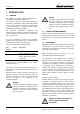
INTRODUCTION 1 INTRODUCTION 1.1 GENERAL The Whisper 3.5 Marine Diesel Generating set is manufactured and marketed by Mastervolt. It is important to read this manual before installing and operating the generating set. Both safety and durability rely very much on the correct identification, installation and a good understanding of ratings, features, design, maintenance and operation procedures.
INTRODUCTION Example 2: Misuse: Long term running with no load or too little load can cause the exhaust to get choked with soot or carbon. Cleaning the exhaust is not covered by guarantee. guarantee certificate, unauthorised repairs could lead to further damage and violate the guarantee conditions.
INTRODUCTION 1.5.1 Identification plate 2 POWER The identification plate gives the nominal maximum continues load in kVA (= kW) calculated with power factor one. When calculating a load one should always take into account the power factor or cos phi of this load. The power should never exceed 3 kW. Power is rated at an ambient temperature of 40°C and a seawater temperature of 25ºC. For higher temperatures the generating set has to be derated. 3 VOLTAGE shows the nominal voltage.
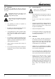
INFORMATION 2 INFORMATION 2.1 SAFETY 2.1.1 General When correctly installed and used in normal circumstances this generating set fulfils EC safety regulations. This generating set could be part of an installation or could be used in a way that additional regulations of the EC or other authorities have to be taken into account. Circumstances could make it also necessary to take additional measures. Be aware of wet conditions and hazardous environments caused by explosive gases etc 2.1.2 2.1.
OPERATION 2.1.5 Operation 2.1.6 The Whisper 3.5 generating set does not have any external moving parts like fans and V-belts and therefore is very safe. Fuels can be flammable. Proper handling limits the risk of fire and explosion. Nevertheless take note of the signs on the generating set which show symbols in a triangle indicating danger. • Avoid refilling the fuel tank while the engine is running. When oil or fuel is leaking do not use the generating set.
INFORMATION 2.2 TRANSPORT, LIFTING AND STORAGE When lifting the generating set avoid any risk of personal injuries, do not stand un-der the generating set.. • Use soft slings to avoid damage • Included in the delivery is a lifting eye, only to be used to take the generator out of the capsule. Do not use to lift the set including the capsule and certainly not including the steel foundation plate ! • After transporting the generating set check for damage before installation.
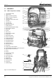
OPERATION 2.4 COMPONENTS 18 19 2.4.
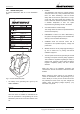
INFORMATION 2.4.2 Local control panel 2.5 2.5.1 1 FUSE 10A (BATTERY CHARGER) 2 FUSE 30A 3 4 START 5 6 GENERATOR CAN START AUTOMATICALLY REMOVE FUSES DURING MAINTENANCE GLOW PULL TO STOP CONTACT / FUEL PUMP 7 AUTOSTART 8 FAILURE 9 START / STOP DIGITAL DIESEL CONTROL PANEL 2.4.
OPERATION monitored and controlled by any MasterBus compatible remote control panel. The MasterView Easy is a MasterBus compatible monitoring and control panel that is standard included in the delivery of the generating set. 2.5.7 1 Refer to the separate operating manual of the MasterView Easy for operation instructions. 2.5.4 It is very important to use the correct oil specification. Very often local oil suppliers recommend a higher class, because they assume that a higher class is allowed.
INFORMATION 2.5.8 Technical data GENERAL Model RPM Alternator Engine Number of cylinders Displacement Bore X stroke Combustion air consumption Continuous power engine Cooling system Cooling water pump Fuel lift pump engine Starting battery (optional) Fuel consumption Control Sound level (ISO 3746): WHISPER 3.5 3000 water cooled, synchronous Kubota diesel, model OC60 (Japan) 1 276 cm3 72x68 mm 0.38 m3/min. at nominal RPM 3 kW nett Indirect cooling by raw water.
MASTERBUS TERMINATOR TO REMOTE PANEL (MASTERBUS NETWORK) 3 14 (1mm2) 13 (1mm2) 3 1 ALARM CONTACT (OPTIONAL) 30 (1mm2) 31 (1mm2) 3 2 1 3 2 1 4 1 5 4 15 5 15 6 6 8 7 7 8 10 10 25 26 27 9 10 5 5 20 21 22 23 24 10 1 1 BATTERY CHARGER WINDING GENERATOR TO GENERATOR AC OUTPUT 9 25 26 27 20 21 22 23 24 12 (1mm2) 11 (1mm2) 31 (1mm2) 30 (1mm2) CURRENT MEASURING TRANSFORMER 6 (1.5mm2) STOP SOLENOID 7 (1.
EN / WHISPER 3.5 / December 2009 / Copyright © 2009 Mastervolt MASTERBUS TERMINATOR TO REMOTE PANEL (MASTERBUS NETWORK) 3 1 14 (1mm2) 13 (1mm2) 3 1 ALARM CONTACT (OPTIONAL) 30 (1mm2) 31 (1mm2) 3 2 1 3 2 1 17 17 15 5 5 15 6 8 6 10 7 10 7 8 10 9 25 26 27 10 5 5 20 21 22 23 24 9 25 26 27 1 CURRENT MEASURING TRANSFORMER 49 (1mm2) 18 (1mm2) 3 (2.5mm2) 16 (2.5mm2) 17 (1mm2) STOP SOLENOID 5 (1.5mm2) 1 6 (1.5mm2) 20 21 22 23 24 19 (1mm2) 17 (1mm2) 4 (2.
OPERATION 2.5.10 Wiring names and colours Wire number Wire name Colour Cross section 1 2 3 4 5* 6 7 8* 9 10 11 12 13 14 15* 16* 17* 18* 19* 22 23* 24 25 26 27 30 31 40 41 49* Battery + Battery – Glow + Start solenoid + Stop solenoid – Stop solenoid + Fuel valve + Fuel valve – Fuel pump + Fuel pump – Charger a Charger b Safety switch + Safety switch – Battery + Battery + Start relay + Glow relay + Battery – Oil pressure + Oil pressure – Exhaust temp. + Exhaust temp. – Engine temp. + Engine temp.
INFORMATION 2.5.
OPERATION 3 OPERATION 3.1 GENERAL The generating set is operational after full installation and filling up with: fuel, engine lubricating oil and cooling liquid, filling the starter battery with acid, connecting the battery to earth and connecting the MasterView Easy remote panel. 3 2 1 1 Filling cap 2 Minimum oil level 3 Maximum oil level Figure 9 3.2 3.2.1 OPERATING INSTRUCTIONS Summarised operating instructions (daily use) Routine "pre-start" checks: 1 Check oil level (refer to figure 9).
OPERATION 3.2.2 Extended operating instructions Check when starting the first time or after a longer period of rest: 1 If there is any damage caused by transport or installation. 2 Check if installation conforms to the installation instructions. 3 Ensure the generating set is free to turn without obstruction. 4 Check all hoses and hose connections for leaks. 5 Check all cables and cable end terminal connections. 6 Check the engine and generator mounting bolts.
OPERATION Checks once the generator is in operation: 1 2 3 Check for abnormal noise or vibration. Check the voltage. Check coolant flow. Always check immediately after starting the generator if cooling water flows at the exhaust outlet. If this is not the case, check the cooling water pump. After having become acquainted with the generator you will be able to recognise the coolant flowing through the system by listening for the noise of the water which is expelled.
MAINTENANCE 4 MAINTENANCE 4.1 ALTERNATOR The alternator does not require any maintenance. Periodic inspection and cleaning is recommended, depending on environmental conditions. However when the alternator has been idle for a long period attention to winding condition is recommended. The condition of windings can be assessed by measurement of insulation resistance to earth. The CAPACITOR should be disconnected during this test. A 500V ‘megger’ or similar instrument should be used.
MAINTENANCE 4.2.4 Replacing fuel filter Filter change depends on contamination of the fuel, but should be done however, at least every 1000 running hours. Before changing the filter, clamp off the supply line. Remove the hoses from filter and attach them on the new filter again. The arrow on the filter housing indicates the direction of the flow. A clogged filter results in a lack of output of the generating set. 4.2.
MAINTENANCE • The air is taken in via the cover on the alternator. Below this cover is a spongy material which filters the air and holds some electrical components which are cooled by the inlet air. This filter does not require regular maintenance. Only in very dusty circumstances this filter should be cleaned. The spongy material can be washed in solvent or replaced. Check the cooling system: The engine oil is indirectly cooled by raw water via an oil cooler/ heat exchanger.
TROUBLE SHOOTING 5 TROUBLE SHOOTING 5.1 ALTERNATOR/ ELECTRICAL FAULTS Beware of parts which are live! Before working on the generator, remove the 30Amp fuse from the local control panel (see figure 3) to prevent the engine from starting 5.1.1 General If any problem should occurs, check basic conditions and examine all external wiring, switch gear and circuit breakers. Also check if measuring instruments give the correct value.
TROUBLE SHOOTING 5.1.2 Failure or warning messages displayed on the remote control panel AC warnings and failures No failure UAC Low UAC High IAC High FAC Low Meaning What to do? None (no failure detected) Generator output voltage too low Generator voltage too high AC output current is too high AC output frequency is too low, engine speeds is too low. AC output frequency is too high, engine speed is too high. Too much load connected to the AC output of the generator -See section 5.1.3, See section 5.
TROUBLE SHOOTING 5.1.3 Other electrical problems Problem No output (Voltage) at all Possible cause • Circuit breaker "off" or faulty fuse What to do? Check switches and fuses and measure directly on the alternator to exclude external causes. Check the engine RPM and adjust (refer to special procedures). Check the residual magnetism and flash the alternator (refer to special procedures). Check by independent excitation if the problem is in the capacitor or in the windings.
TROUBLE SHOOTING 5.2 ENGINE FAULTS well starting problems almost always originate from lack of fuel or air bubbles in the fuel pipes. Before working on the generator, remove the 30Amp fuse from the local control panel (see figure 3) to prevent the engine from starting 5.2.1 When the engine does not start instantly, prolonged cranking can fill up the exhaust system with cooling water because of the water injected exhaust.
TROUBLE SHOOTING 5.2.3 Other engine related problems Problem Possible cause What to do? Diesel engine fails to crank, the starter makes clicking noises, or the engine cranks very slowly • Almost certainly this is an electrical problem. The remote control panel will indicate a failure code related to the DC voltage (see 5.1.2) • One other possibility is that the engine is locked by water in the cylinder or there is other severe damage.
TROUBLE SHOOTING Problem Possible cause • Air in the fuel pipes What to do? Bleed air from fuel system (refer to maintenance section). Have the injector tested and cleaned if • Blocked injector. necessary. Adjust valve clearance. • Wrong valve clearance. • Temporarily hunting (this will disappear when engine has run in). Engine speed drops • • • • Too much oil. Lack of fuel. Lack of intake air. Choked exhaust system, exhaust blocked, rubber exhaust hose kinked.
TROUBLE SHOOTING Problem Possible cause • Fuel injector faulty. What to do? Replace injector. • • • • Readjust valve clearance Use better quality diesel. Use better quality oil. Increase load and have the engine run for a few hours Valve clearance incorrect. Poor fuel quality. Poor quality lubricating oil. Continuous running with very low load. Loss of power ● Wrong measurement. Check if the load is measured correctly.
TROUBLE SHOOTING 5.3 5.3.1 SPECIAL PROCEDURES ALTERNATOR across the diodes, or the ESD capacitor. Replace the diodes, the suppressors and the capacitors. Residual voltage check / excitation procedure When residual magnetism disappears there is no residual voltage. Residual magnetism can disappear after the generating set being out of service for a long period or suffered a short circuit. This can be solved by charging the capacitor ("flashing") independently with a small 9 Volt battery.
TROUBLE SHOOTING 5.4 5.4.1 SPECIAL PROCEDURES ENGINE Setting the RPM RPM is set by the manufacturer and should not need readjustment! However a very slight offset after running in could occur. RPM can be measured by a frequency meter. Before readjustment check any other explanation for the wrong speed. Engine speed is set at the factory at nominal 3000 (50 Hz) RPM. A RPM drop of 5% at full load is acceptable. Therefore a no load setting should be at ± 3150 RPM = 52.5 Hz.
TROUBLE SHOOTING 5.4.4 How-ever one can take off the complete alternator housing. Disassembling instructions It could be necessary for repair or checks to disassemble the generating set. One can take off the white cover easily for regular maintenance and inspection. For further repair or inspection one can take off the upper green part as well.
SPARE PARTS LIST 6 SPARE PARTS LIST A parts manual in English is available as an option; number: 50200180(***). A work shop manual in English is available as an option; number: 50200170(***). We recommend the following spares for service and maintenance.
SPARE PARTS LIST Figure 18: Waterpump type K EN / WHISPER 3.
MAINTENANCE LOG MAINTENANCE LOG first service after 50 hours: hour counter: next service (every 150 hours) hour counter: 36 remarks Copyright © 2009 Mastervolt / December 2009 / WHISPER 3.
NOTES NOTES EN / WHISPER 3.
NOTES NOTES 38 Copyright © 2009 Mastervolt / December 2009 / WHISPER 3.
NOTES NOTES EN / WHISPER 3.
Snijdersbergweg 93, 1105 AN Amsterdam, The Netherlands Tel : + 31-20-3422100 / F ax : + 31-20-6971006 www.mastervolt.com / info@mastervolt.