INSTALLATION MANUAL WHISPER 3.5M - 3000 RPM - Marine diesel generating set 230V / 50Hz MasterBus controlled Art.nr. 50261141 MASTERVOLT Snijdersbergweg 93, 1105 AN Amsterdam The Netherlands Tel.: +31-20-3422100 Fax.: +31-20-6971006 www.mastervolt.
CONTENTS This manual applies to the Mastervolt Whisper 3.5 Marine Diesel Generating set controlled by MasterBus first launched in April 2008. For earlier models refer to other manuals available on our website: www. mastervolt.com Copyright © 2009 Mastervolt. All rights reserved. Reproduction, transfer, distribution or storage of part or all of the contents in this document in any form without the prior written permission of Mastervolt is prohibited. CONTENTS: 1 INSTALLATION ..............................
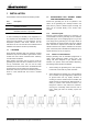
INSTALLATION 1 INSTALLATION This installation manual is valid for the following models: 1.2 Part number 51200500 Position the generating set as low as possible in the vessel. As the generating set is already secured to the base frame by means of flexible engine mountings, the frame can be mounted directly to the vessel’s main structure. Description Whisper 3.5 / 230V 3000rpm wet exhaust MasterBus controlled 51200506 Whisper 3.
INSTALLATION 3 1.3 Never connect the base of the generating set directly to bulkheads or tanks. VENTILATION The generating set normally draws air from the engine room. Engine rooms with natural ventilation must have vent openings of adequate size and location to enable the generating set to operate without overheating. To allow an ample supply of air within the temperature limits of the generating set an opening of at least 100 cm2 is required.
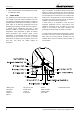
INSTALLATION 1.4 CONNECTIONS The generating set comes supplied with all supply lines and output cable (i.e. electric cables, cooling water connections, exhaust, fuel lines etc.) already connected to the engine and generator. The supply lines are fed through the capsule’s front base. The connections are marked as shown in figure 2. All electrical connections, cable types and sizes must comply with the appropriate national regulations. Supplied cables are rated for ambient temperatures up to 70°C.
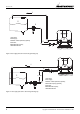
INSTALLATION 1 5 3 1 Fuel return; 2 Fuel supply; 3 Prefilter / water separator (optional); 5 Fuel tank; 6 Standard fuel lift pump; 7 Standard fuel filter. 2 6 7 Figure 3: Fuel supply (fuel tank is above the generating set) 1 2 6 5 7 > 1m 4 3 1 Fuel return; 2 Fuel supply; 3 Prefilter / water separator (optional); 4 Extra fuel lift pump (optional); 5 Fuel tank; 6 Standard fuel lift pump; 7 Standard fuel filter. Figure.
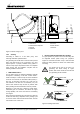
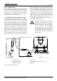
INSTALLATION MAX. 150CM (60") MIN. 60CM (24") MIN. 3CM (1,2") 5CM (2") 5 2 6 MAX. 10CM (4") 1 3 4 7 1 Water level 2 Water/exhaust separator 3 Seacock 4 Waterlock 5 Air vent; 6 Water strainer; 7 Seacock. Figure 5: Internal cooling system 1.4.2 Cooling Intercooling is based on a raw water pump, heat exchanger and water-injected exhaust. The generating set should have its own sea water (coolant water) inlet and should not be connected to any other engine systems.
INSTALLATION On motorboats and on sailing boats the water scoop for a generating set should be fitted with the opening faced backwards to prevent water being forced in during sailing. Use a sealant when mounting the skin fitting. OPEN 3 WATER STRAINER Use an appropriate water strainer with connections of 12.5 mm (1/2"). Install the water strainer in a well accessible position, (refer to figure. 5, ref 6) 5 cm above the waterline.
INSTALLATION 1.4.3 Exhaust system Water is injected in the exhaust system of the generating set. In this way the cooling water that has passed the heat exchanger is mixed with the exhaust gases. Temperature and volume of the gases are thereby reduced considerably, so that a rubber exhaust hose can be used and the level of noise is reduced as well. A Max. length A - B = 2.5m (8 ft.
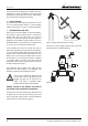
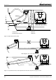
INSTALLATION MIN. 3CM (1,2") Ø 40 mm Ø 40 mm MAX. 120CM (48") MIN. 60CM (24") 2 MAX. 10CM (4") Ø 40 mm 1 3 4 1 Water level 2 Water/exhaust separator 3 Seacock 4 Waterlock Figure 10: Super silent exhaust system Max. length A - B = 2.5 m. (8 ft) A Ø 40 mm B Ø 40 mm Ø 40 mm Ø 40 mm Figure 11: Only after the exhaust / water separator the exhaust hose may have a length up to 7,5m 10 Copyright © 2009 Mastervolt / October 2009 / WHISPER 3.
INSTALLATION 2 "SUPER SILENT" EXHAUST SYSTEM See figure 10. In order to reduce the noise level of the generating set to a minimum, an option to reduce the exhaust noise further (especially exhaust water splashing) is an exhaust/water separator. The exhaust/water separator allows the cooling water to be ejected through a line separate from the exhaust fumes and also functions as a goose neck to prevent water from flooding the engine.
INSTALLATION If the generating set and the exhaust system have been installed correctly, neighbouring boats will not be disturbed by generating set noise, With the "super silent" exhaust system, generating set noises are almost inaudible. For optimal noise reduction, the sea water outlet from the exhaust/water separator (center outlet on the unit) should be installed below the water level to eliminate noisy splashing of the effluent sea water.
INSTALLATION 1 See figure 15 Insert a MasterBus terminating device into one of both communication ports (it doesn’t matter which one) of the Digital Diesel Control Panel on the generating set. Insert the communication cable in the other communication port Rear side MasterView Easy MasterBus terminating device MasterBus communication cable Figure 18 o Figure 16 2 See figure 16. Connect the other end of the communication cable to one of both communication ports of the MasterView Easy.
INSTALLATION Connection of an emergency stop / fire alarm switch To connect an emergency stop button or to stop the generator automatically in case of a fire alarm, you can use the bypass connection between wires 13 and 14 that come from the The Digital Diesel Control Panel. See fig. 19. To do so, remove the top cover plate of the connection box to get access to the wiring loom.
INSTALLATION 3 OTHER RECOMMENDATIONS AND WARNINGS The battery should be secured for seagoing conditions and the terminals should be insulated. For extra safety the battery can be enclosed in a wooden, plastic, Fiberglas etc. (non metal) box. Even when the earth return system is applied a negative battery cable should be used and the vessel should not to be used as a conductor. In the negative battery cable a 250 Amp starter battery switch could be applied to switch off the battery.
INSTALLATION 2 GROUNDING The AC alternator windings are not grounded. Measures against earth insulation failures are often subject to local regulations. The housing of the alternator and all other metal parts are grounded. For safety reasons connect the main ships ground to negative point of the generating set start battery. When an ungrounded return DC system or positive grounded DC system is applied the battery negative should not be connected to the main ships ground.
INSTALLATION SPECIFICATIONS 2 INSTALLATION SPECIFICATIONS 2.1 WHISPER 3.5 INSTALLATION TABLE Generating set 2.2 1 Check if a siphon breaker (air vent) is necessary and has been installed and that the drain is without bents and air can flow in freely. 2 Open the seawater inlet valve and check all water connections. Check if the strainer is installed above the seawater level. 3 Check if the exhaust system is properly installed.
INSTALLATION SPECIFICATIONS 12 Check when the generating set is running, the delay of 3 – 10 seconds in the power source selector transfer. 13 Check voltage and frequency under ‘no load’ conditions. 14 Check voltage and frequency under ‘full load’ conditions. 16 Close the sound shield and check the noise level. 17 Stop the generating set and check the engine again for leakages of oil, fuel or water. Installation checklist www.mastervolt.com. Commissioning form www.mastervolt.com.
INSTALLATION SPECIFICATIONS 2.5 INSTALLATION MATERIALS WHISPER 3.5 Generator battery positive (+) Generator battery negative (–) Figure 24: Installation materials battery installation kit BATTERY INSTALLATION KIT 55 Ah pos.
INSTALLATION SPECIFICATIONS Generator fuel in Generator fuel out Figure 25: Installation materials fuel supply kit FUEL SUPPLY KIT pos.
INSTALLATION SPECIFICATIONS Generator cooling water inlet Bypass cooling water out WATER INLET KIT 1/2” (12.5 mm) Bypass cooling water in SYPHON BREAKER KIT 1/2” (12.5 mm) Figure 26: Installation materials Water inlet kit and Syphon breaker kit WATER INLET KIT 12.5 mm pos.
INSTALLATION SPECIFICATIONS According to ABYC recommendations all hose connections must be fitted with two hose clamps Maximum torque hose clamps: 12Nm / 105 InLbs Generator exhaust Figure 27: Installation materials “Delta” exhaust kit ø 40 mm (1 5/8”) and water separator kit 40 mm (1 5/8”) “DELTA” EXHAUST KIT Ø 40 mm (1 5/8”) pos.
INSTALLATION SPECIFICATIONS Figure 28: installation materials base plate kit BASE PLATE KIT for Whisper 3.5 (3000 rpm) pos. 61 62 63 64 65 66 67 TOTAL qty 4 1 4 4 4 4 4 article no 50230552 50230012 50211449 50211251 50211438 50211447 50211241 50230207 description Rubber mounting up to 70 kg RAB3 HD base plate 3500 yellow zinc plated Washer spring SP M12 Bolt hexagonal socket ZP M12x40 Washer SP M10x30x1,5 Washer spring SP M10 Bolt hexagonal socket ZP M10x25 BASE PLATE KIT WHISPER 3.5 EN / WHISPER 3.
MASTERBUS TERMINATOR TO REMOTE PANEL (MASTERBUS NETWORK) 3 14 (1mm2) 13 (1mm2) 3 1 ALARM CONTACT (OPTIONAL) 30 (1mm2) 31 (1mm2) 3 2 1 3 2 1 4 4 1 5 5 15 6 6 15 7 7 8 10 10 25 26 27 9 8 10 5 5 20 21 22 23 24 10 1 1 BATTERY CHARGER WINDING GENERATOR TO GENERATOR AC OUTPUT 9 25 26 27 20 21 22 23 24 12 (1mm2) 11 (1mm2) 31 (1mm2) 30 (1mm2) CURRENT MEASURING TRANSFORMER 6 (1.5mm2) STOP SOLENOID 7 (1.
EN / WHISPER 3.5 / October 2009 / Copyright © 2009 Mastervolt MASTERBUS TERMINATOR TO REMOTE PANEL (MASTERBUS NETWORK) 3 1 14 (1mm2) 13 (1mm2) 3 1 ALARM CONTACT (OPTIONAL) 30 (1mm2) 31 (1mm2) 3 2 1 3 2 1 17 17 15 5 5 15 6 8 6 10 7 10 7 8 10 9 25 26 27 10 5 5 20 21 22 23 24 9 25 26 27 1 CURRENT MEASURING TRANSFORMER 49 (1mm2) 18 (1mm2) 3 (2.5mm2) 16 (2.5mm2) 17 (1mm2) STOP SOLENOID 5 (1.5mm2) 1 6 (1.5mm2) 20 21 22 23 24 19 (1mm2) 17 (1mm2) 4 (2.
DIAGRAMS & DRAWINGS 3.2 WIRING NAMES AND COLOURS Wire number Wire name Colour Cross section 1 2 3 4 5* 6 7 8* 9 10 11 12 13 14 15* 16* 17* 18* 19* 22 23* 24 25 26 27 30 31 40 41 49* Battery + Battery – Glow + Start solenoid + Stop solenoid – Stop solenoid + Fuel valve + Fuel valve – Fuel pump + Fuel pump – Charger a Charger b Safety switch + Safety switch – Battery + Battery + Start relay + Glow relay + Battery – Oil pressure + Oil pressure – Exhaust temp. + Exhaust temp. – Engine temp.
DIAGRAMS & DRAWINGS 3.
DIAGRAMS & DRAWINGS 3.4 DIMENSIONS MASTERVIEW EASY PANEL 37 (1.46) 113 (4.45) 37 (1.46) 90 (3.54) 113 (4.45) 27 (1.06) 10 (0.39) 90 (3.54) Figure 31: Dimensions of the panel without and with outer casing. All dimensions are in mm (inch) 3.5 DIMENSIONS WHISPER 3.5 Box dimensions: Top view Service side M12 305 [12.0] • width: • depth: • height: 505 mm [19.9 inch] 400 mm [15.7 inch] 500 mm [19.7 inch] • weight: 104 kg [229 Lbs] 410 [16.1] 430 [16.
MASTERBUS 4 MASTERBUS 4.1 monitoring, control and configuration of all connected MasterBus equipment. WHAT IS MASTERBUS? All devices that are suitable for MasterBus are marked by the MasterBus symbol. MasterBus is a fully decentralized data network for communication between the different Mastervolt system devices. It is a CAN-bus based communication network which has proven itself as a reliable bus-system in automotive applications.
MASTERBUS 4.3 HOW TO NETWORK SET UP A MASTERBUS Each device that is suitable for the MasterBus network is equipped with two data ports. When two or more devices are connected to each other through these ports, they form a local data network, called the MasterBus. Keep the following rules in mind: The electric power for the network comes from the connected devices. At least one device in the network should have powering capabilities (see specifications).
NOTES NOTES EN / WHISPER 3.
MASTERVOLT Snijdersbergweg 93, 1105 AN Amsterdam, The Netherlands Tel : + 31-20-3422100 / F ax : + 31-20-6971006 www.mastervolt.com / info@mastervolt.