
Instruction Manual
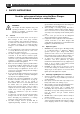

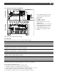
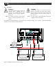
Table Of Contents
- 1 GENERAL INFORMATION
- 2 SAFETY INSTRUCTIONS
- 3 INSTALLATION
- 3.1 Location
- 3.2 Connections
- 3.3 Wiring
- 3.4 Battery capacity
- 3.5 Battery isolator
- 3.6 Connection of second battery (3A output)
- 3.7 Temperature sensor
- 3.8 Voltage sense
- 3.9 Alarm function
- 3.10 RJ12 splitter for enclosure C2
- 3.11 Overview connection compartment
- 3.12 Materials
- 3.13 Connection
- 3.14 Installation step-by-step
- 3.15 Commissioning after installation
- 3.16 Decommissioning
- 3.17 Storage and transportation
- 4 DIP SWITCH SETTINGS
- 5 OPERATION
- 6 MASTERBUS
- 7 TROUBLE SHOOTING
- 8 TECHNICAL DATA

Mass 24/50, 24/75, 24/100, 48/25, 48/50 – User and Installation Manual
9
3.11 Overview connection compartment
C2 ENCLOSURE
1 Screw terminals AC input: L1, N, PE
(models 24/50 3ph and 24/100 3ph:
L1, L2, L3, PE)
2 Earth stud
3 MasterBus connector
4 MasterBus connector
5 Output (battery) positive connector
(maximum 3A)
6 RS232/Temperature sensor connector
7 Analog/Temperature sensor connector
8 Output (battery) positive connector
9 Output (battery) negative connector
10 Voltage sense/ potential free alarm
contact
C3 ENCLOSURE
Figure 3. Overview connections Mass Charger
3.12 Materials
Make sure you have all the parts you need to install the Mass Charger:
Product
Quantity
Mass Charger (included)
1
Battery temperature sensor with cable and plug (included)
1
DC cable to connect the positive DC connection (+) of the Mass Charger to the positive pole of the DC
distribution; for specifications see section 3.3.3 on page 6
1
DC cable to connect the negative DC connection (–) of the Mass Charger to the negative pole of the DC
distribution; for specifications see section 3.3.3 on page 6
1
DC fuse holder with a DC fuse, to be integrated in the positive DC cable
1
Screws/bolts (Ø 6mm) (with plugs) to mount the cabinet to a surface. Use mounting materials which are
suitable to carry the weight of the Mass Charger
4
AC cable* to connect the AC input to an external power source (e.g. a shore connection or a generator set)
1
Batteries. See section 3.4 on page 7 for recommended capacity
X
Appropriate and reliable cable terminals, cable lugs, battery terminals and cord end terminals
X
* Double insulated three-wire cable with wire colours according to the locally applicable regulations. The applicable length and
wire diameter depend on the electrical installation (see section 3.3.1 on page 6).
We recommend as a minimum tool kit:
• Socket wrench 13mm to fix the DC input (battery) cables
• Flat blade screwdriver 1.0 x 4.0mm to fix the screw terminals
• Tools to fix the screws/bolts (Ø 6mm) with plugs to mount the cabinets to a surface
• Philips screwdriver to open the connection area of the Mass Charger
• 2mm flat blade screwdriver for the sense terminal (see Figure 3, point 10).