
Instruction Manual
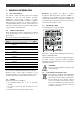
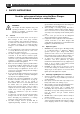

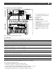
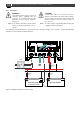
Table Of Contents
- 1 GENERAL INFORMATION
- 2 SAFETY INSTRUCTIONS
- 3 INSTALLATION
- 3.1 Location
- 3.2 Connections
- 3.3 Wiring
- 3.4 Battery capacity
- 3.5 Battery isolator
- 3.6 Connection of second battery (3A output)
- 3.7 Temperature sensor
- 3.8 Voltage sense
- 3.9 Alarm function
- 3.10 RJ12 splitter for enclosure C2
- 3.11 Overview connection compartment
- 3.12 Materials
- 3.13 Connection
- 3.14 Installation step-by-step
- 3.15 Commissioning after installation
- 3.16 Decommissioning
- 3.17 Storage and transportation
- 4 DIP SWITCH SETTINGS
- 5 OPERATION
- 6 MASTERBUS
- 7 TROUBLE SHOOTING
- 8 TECHNICAL DATA

6
Mass Charger 12/75-3, 12/100-3, 24/40-3, 24/60-3 – User and Installation Manual
3 INSTALLATION
During installation and commissioning of the Mass
Charger, the important safety instructions are applicable at
all times. See chapter 2 on page 4.
Please check the contents of the box before you start with
the installation. The contents of the box need to be:
• the Mass battery charger;
• battery temperature sensor (incl. 6m cable);
• a MasterBus terminator;
• the user manual.
If one of these items is missing, please contact your
Mastervolt dealer.
3.1 Location
Choosing a location to install:
• Install the Mass Charger in a well-ventilated room
protected against rain, snow, spray, vapour, bilge,
moisture and dust.
• Ambient temperature: 0…60°C/32°F…140°F; (power
derating above 40°C/104°F to decrease the internal
heat sink temperature).
• Humidity: 0-95% non-condensing.
• Never use the Mass Charger at a location where there
is danger of gas or dust explosions
• Mount the Mass Charger in such a way that
obstruction of the airflow through the ventilation
openings is prevented. No objects must be located
within 10cm/4inch around the Mass Charger.
• Mount the Mass Charger vertically, with the connecting
cables downwards.
• Do not install the Mass Charger in the same
compartment as the batteries. Do not mount the Mass
Charger straight above the batteries because of
possible corrosive sulphur fumes.
3.2 Connections
Before making the connection between the battery charger
and the system, be sure that the AC and DC system are
switched off. Remove the fuses to protect yourself against
unexpected start up.
3.3 Wiring
CAUTION!
The wire and fuse sizes stated in this manual
are given as example only. Prescribed wire
and fuse sizes may be different due to local
applicable regulations and standards.
3.3.1 AC wiring
Check if the voltage of your mains source or generator
corresponds with the AC input voltage of the battery
charger as mentioned on the type number plate. See
section 1.4 on page 3.
It is important that the green/ yellow earth wire is ± 1 cm
(0.4 inch) longer than the other wires. By accidentally
pulling at the cable, the earth wire stays connected to the
Mass Charger longer which offers additional safety.
For a safe installation the correct wire cross section must
be applied. Do not use a cross section that is smaller than
indicated. See the following table to select the appropriate
cross section for the AC wiring (up to 6m/20ft length):
AC Current
Minimum cross section:
6-12A
1.5mm²
14AWG
12-20A
2.5mm²
12AWG
20-32A
4.0mm²
10AWG
Connection of AC wiring and recommended colours
• 230V [120V] installations:
Wire colour
Meaning
Must be
connected to:
Brown or black [black]
Phase
L1
Blue [white]
Neutral
N
Green/yellow [green]
Earth
PE/GND
• 400V installations (Mass 24/50 3ph & 24/100 3ph):
Wire colour
Meaning
Must be
connected to:
Brown/black/grey
Phase
L1, L2, L3
Green/yellow
Earth
PE/GND
3.3.2 AC safety grounding
WARNING!
The ground wire offers protection only if the
cabinet of the Mass Charger is connected to
the safety ground. Connect the ground
terminal (PE/GND) to the hull or the chassis.
CAUTION!
For safe installation it is necessary to insert an
RCD (Residual Current Device; earth leakage
switch) in the AC input circuit of the Mass
Charger.