
Instruction Manual
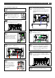
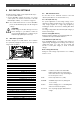
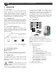
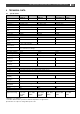
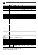
Table Of Contents
- 1 GENERAL INFORMATION
- 2 SAFETY INSTRUCTIONS
- 3 INSTALLATION
- 3.1 Location
- 3.2 Connections
- 3.3 Wiring
- 3.4 Battery capacity
- 3.5 Battery isolator
- 3.6 Connection of second battery (3A output)
- 3.7 Temperature sensor
- 3.8 Voltage sense
- 3.9 Alarm function
- 3.10 RJ12 splitter for enclosure C2
- 3.11 Overview connection compartment
- 3.12 Materials
- 3.13 Connection
- 3.14 Installation step-by-step
- 3.15 Commissioning after installation
- 3.16 Decommissioning
- 3.17 Storage and transportation
- 4 DIP SWITCH SETTINGS
- 5 OPERATION
- 6 MASTERBUS
- 7 TROUBLE SHOOTING
- 8 TECHNICAL DATA

14
Mass 24/50, 24/75, 24/100, 48/25, 48/50 – User and Installation Manual
5 OPERATION
5.1 Introduction
The Mass charger is a fully automatic, high efficiency
battery charger/rectifier. The Mass Charger not only
charges batteries rapidly and safely, it supplies the
connected consumers at the same time. In addition, the
Mass Charger is secured against short circuit, overload
and high temperatures in an industrial environment.
5.2 Switching on/off
Activate the Mass Charger by switching the main switch to
the ON position. When no error is present, the charger LED
illuminates green and the Mass Charger starts charging.
Move the switch to the OFF position to switch off the Mass
Charger!
5.3 The 3-step+ charge process
The Mass charger is equipped with an intelligent 3-step+
charge characteristic which takes care of an optimal
charge of your batteries. See Figure 6 and Figure 9 (page
22) for more details.
Figure 6. the 3-step+ charge process.
5.4 Reset the Mass Charger
Set the main switch to off.
Switch on again.
The Mass Charger automatically resumes operation in
Bulk stage after it was disconnected from an AC source.
5.5 Equalize mode
An equalizing charge can be necessary after very deep
discharges and/or inadequate charges. This has to be
carried out according to the specifications of the battery
manufacturer.
WARNING!
Equalization is ONLY applicable for flooded
batteries and will damage Gel/AGM/Spiral type
batteries!
Incorrect use of the equalize mode may lead to hazardous
situations. During equalizing the batteries are brought into
the gas state and permitted load voltages may be
exceeded (refer to Figure 10 on page 23 for
characteristics). For these reasons the equalizing mode
should only be used by trained technical engineers.
The equalizing mode can only be started when the Mass
Charger is in float operation. To start the equalize mode,
select Equalize in the MasterBus device settings (see
section 6.3 on page 15).
5.6 LED indicators
Figure 7. Front panel of the battery charger
During normal operation the charger LED (6) is green.
When all charge process status LEDs (1 to 5) are on, the
battery is fully charged. For details refer to Figure 9 on
page 22.
1…5
Status LEDs charge process
6
Charger status LED:
˗ Green = on
˗ Off = off
˗ Red = fault condition:
+
: Battery sense error
+
: Charger temperature too high
+
: Short circuit indication, charger will reduce
the charge current to 25%
+
: DC error, DC voltage too low or too high
+
: Temperature sense error
7
Status LED MasterBus communication:
˗ Green = MasterBus communication
˗ Off = no MasterBus communication
8
Main or on/off switch
9...13
Status LEDs charge current
13
5
4
3
2
1
7
6
8
9
10
11
12