
Instruction Manual
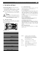
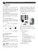
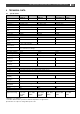
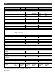
Table Of Contents
- 1 GENERAL INFORMATION
- 2 SAFETY INSTRUCTIONS
- 3 INSTALLATION
- 3.1 Location
- 3.2 Connections
- 3.3 Wiring
- 3.4 Battery capacity
- 3.5 Battery isolator
- 3.6 Connection of second battery (3A output)
- 3.7 Temperature sensor
- 3.8 Voltage sense
- 3.9 Alarm function
- 3.10 RJ12 splitter for enclosure C2
- 3.11 Overview connection compartment
- 3.12 Materials
- 3.13 Connection
- 3.14 Installation step-by-step
- 3.15 Commissioning after installation
- 3.16 Decommissioning
- 3.17 Storage and transportation
- 4 DIP SWITCH SETTINGS
- 5 OPERATION
- 6 MASTERBUS
- 7 TROUBLE SHOOTING
- 8 TECHNICAL DATA

Mass 24/50, 24/75, 24/100, 48/25, 48/50 – User and Installation Manual
13
4 DIP SWITCH SETTINGS
The Mass Charger settings can be adjusted in two ways:
• By means of DIP switches;
• Via the MasterBus network (by means of a remote
control panel or an interface connected to a PC with
MasterAdjust software); see section 6.3 on page 15.
Note: Once a DIP switch has been set to On, MasterBus
presets are disabled but people can still change the
settings!
CAUTION!
Invalid settings of the Mass Charger can cause
serious damage to your batteries and/or the
connected load! Adjustments of settings may be
undertaken by qualified personnel only!
4.1 DIP switch operation
The Mass Charger has six DIP switches. These switches
are operated by flipping the levers to the other position,
using a small screwdriver.
Figure 5. DIP switches
4.2 DIP switch functions
See the table for the functional overview of the DIP
switches (DIP switch 6 is reserved for future use).
Force Float (DIP switch 1)
For special applications a fixed charge voltage can be
required. The battery charger allows you to change the 3-
step+ charge program to a single stage program by
activating the function "Force Float", switching DIP switch
1 to "ON".
The charge voltage will be fixed at 26.5V (24V charger) or
53V for a 48V charger.
Traction setting (DIP switch 2)
Setting for traction charging: +0.7/1.4V during bulk and
+0.4/0.8V in absorption for 24/48V batteries.
Gel/AGM batteries (DIP switch 3)
Some Gel/AGM batteries need a higher float voltage for
optimal charge. Changing the float voltage can be done by
setting DIP switch 3 to "ON". The float voltage will
increase to 27.6V (24V charger) or 55.2V for a 48V
charger.
Diode setting (DIP switch 4)
Setting for +0.6V voltage compensation in case a battery
isolator is used.
DIP SWITCH
5
4
3
2
1
Standard
0
0
0
0
0
Diode
0
1
0
0
0
Gel/AGM
0
0
1
0
0
Diode + Gel/AGM
0
1
1
0
0
Traction
0
0
0
1
0
Traction + Diode
0
1
0
1
0
ContMon + Traction
0
0
1
1
0
ContMon + Traction + Diode
0
1
1
1
0
ForceFloat
0
0
0
0
1
ForceFloat + Diode
0
1
0
0
1
ForceFloat + Gel/AGM
0
0
1
0
1
ForceFloat + Diode + Gel/AGM
0
1
1
0
1
ContMon
0
0
0
1
1
ContMon + Diode
0
1
0
1
1
ContMon + Gel
0
0
1
1
1
ContMon + Diode + Gel/AGM
0
1
1
1
1
Lithium-ion (Mastervolt MLI)
1
0
0
0
0
Lithium-ion + Diode
1
1
0
0
0
Lithium-ion + ForceFloat
1
0
0
0
1
Lithium-ion + ContMon
1
0
0
1
1
1 = On; 0 = Off
ContMon:
Continuous monitor mode. MasterBus,
RS232 and DC alarm stay functioning at
mains failure. Remote stays functioning if it
has its own power source.
Diode:
Diode compensation on (+0.6V)
Gel/AGM:
Gel/AGM compensation on (during float
+1.1V or 2.2V)
Traction
Traction charging (+0.7 or 1.4V during bulk
and +0.4 or 0.8V in absorption).
Force float:
One step charge program with fixed float
voltage.